
Digital TV antenna

a digital tv and antenna technology, applied in the field of antennas, can solve the problems of intermodulation and other types of interference, impair the reception of digital tv in most of the commercialized devices in the country, and the antenna is not able to simultaneously receive signals having polarization, so as to reduce the size of the structure

Active Publication Date: 2017-01-24
INST PRESBITERIANO MACKENZIE
View PDF4 Cites 1 Cited by
  • Summary
  • Abstract
  • Description
  • Claims
  • Application Information

AI Technical Summary

Benefits of technology

The present invention aims to provide an antenna that can be easily installed and used in indoor or outdoor settings. It is small in size, can be fixed or mobile, and has the capability to simultaneously receive signals across the full range of digital TV frequencies. The antenna is also able to block out unwanted signals such as radio broadcasts, before they reach the receiver device.

Problems solved by technology

Thus, the conventional antennas will supply a digital receiver with unneeded signals, which may cause intermodulation and other types of interferences.
Particularly, it is known that radio broadcasting signals in Frequency Modulated (FM), which occupy the frequency range from 88 MHz to 108 MHz, significantly impair the digital TV reception in most of the devices commercialized in the country.
However, the antenna is not able to simultaneously receive signals having polarizations other than the horizontal.
In this case, in which it is only possible an adequate reception of horizontally polarized signals, all the receptions have to be mandatorily made horizontally.
These antennas do not have means to allow the user to receive signals in multiple and different polarizations.
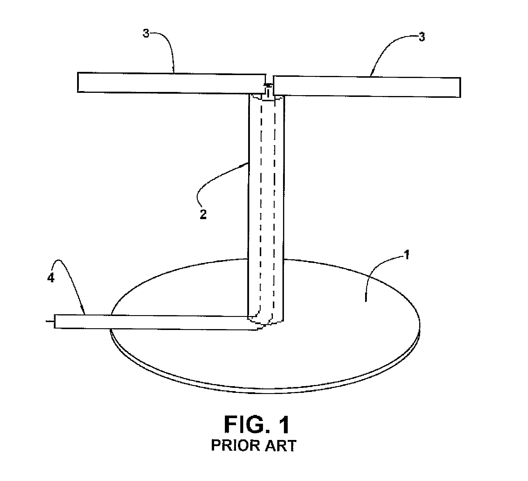
Besides the operational limitation mentioned above, this known type of antenna has a dimension and shape which makes difficult the aesthetic harmonization with the indoor environment in which they are installed.
Another drawback of these known antennas is due to the fact that they are not suitable to be installed outdoors or in vehicles.
Another important factor that degrades the digital TV signal reception is the interference caused by the FM radio transmitters.
These hi-power analog signals, irradiated by the transmission antennas of the FM stations scatter throughout the spectrum and interfere in the reception of the digital TV signals.
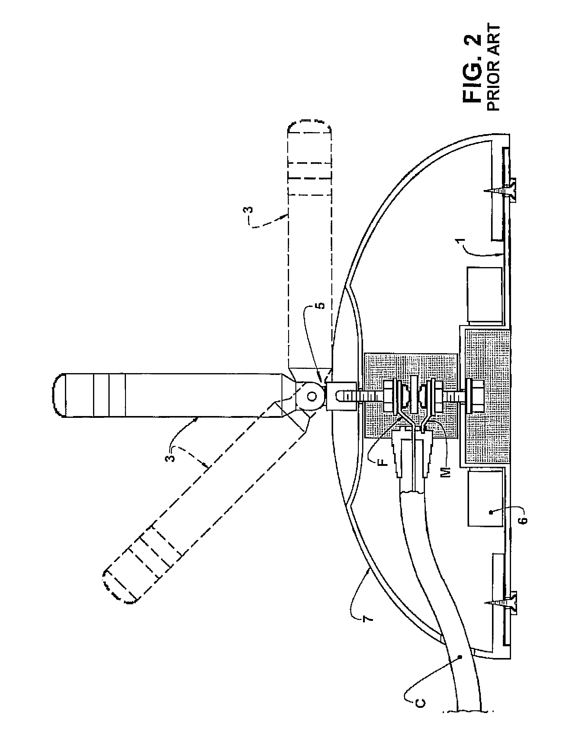
Although eliminating some of the disadvantages of the previous antennas, said last construction still presents a few drawbacks, including a relevant signal loss through the hinge, especially over time and with a progressive deterioration of the elements articulated to each other.
Moreover, said previous construction is relatively complex, using multiple elements for building the base and for promoting the connection of the elements of the coaxial cable to the metallic base and to the irradiating element through the hinge, adding cost to the product and impairing the integral transmission of the incoming signals to the coaxial cable connected to the receiver device.
Still another drawback of said prior solution is related to the fact that it does not include any filter element provided between the irradiating element and the coaxial cable, in order to block de radio broadcast signals in modulated frequency occupying the frequency range from 88 MHz to 108 MHz, which, as mentioned before, significantly impair the reception of the digital TV signals in most part of the devices sold in Brazil.
The filters provided inside the receiver device itself are not able to prevent undesirable interferences of said radio broadcast signals in the reception of the digital TV signals.

Method used


Image

  • Digital TV antenna
  • Digital TV antenna
  • Digital TV antenna

Examples


Embodiment Construction

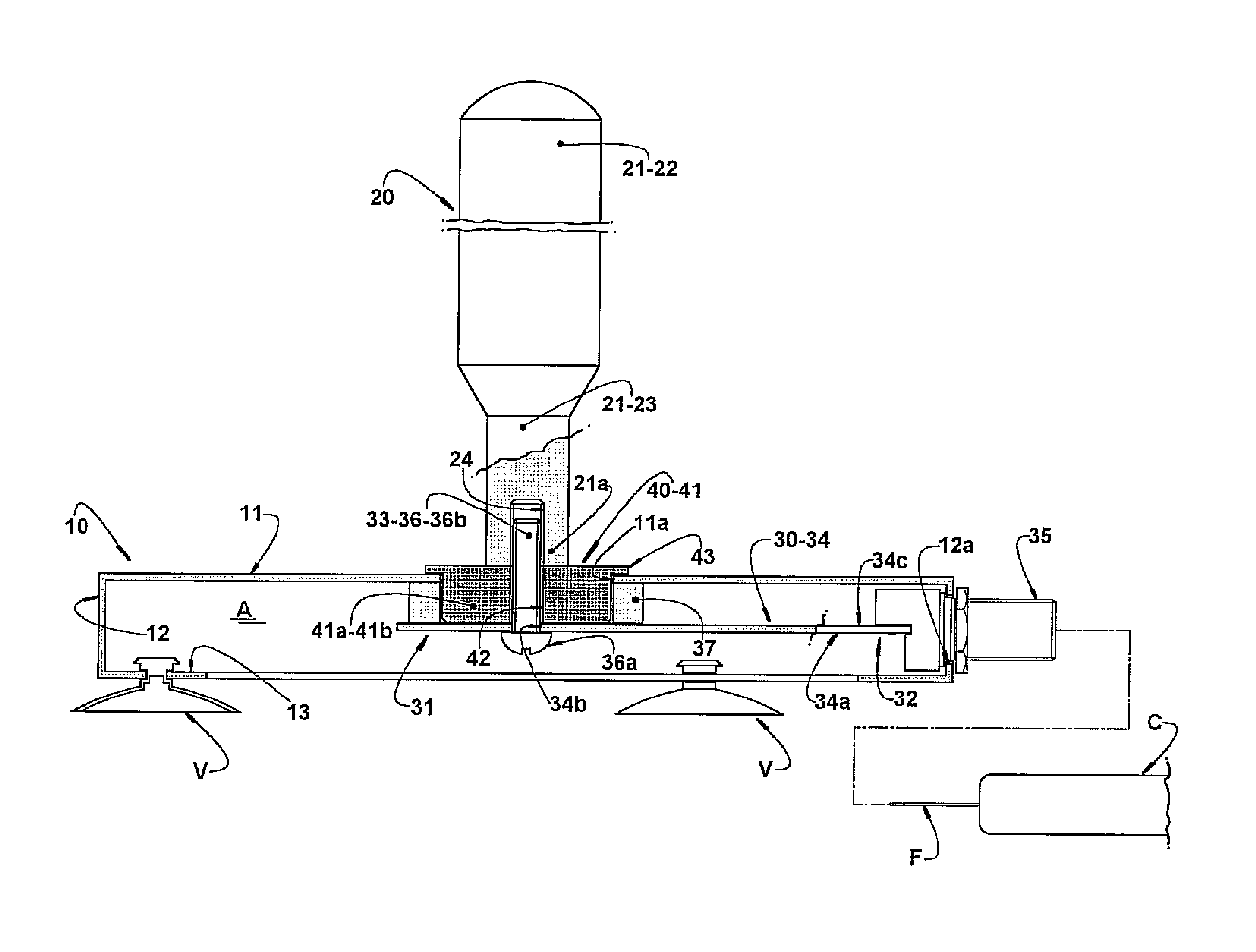
[0026]As illustrated in the attached drawings, the present digital TV antenna comprises a metallic base 10, preferably pressed from an aluminum plate having a thickness for example of 2 mm and having, for example, a substantially circular contour, said base 10 internally defining a housing A.

[0027]The base 10 comprises a top wall 11 provided with a through hole 11a, which limits, superiorly, the housing A and incorporates, in a peripheral edge, a skirt 12 which peripherally limits the housing A and presents a radial window 12a. The skirt 12 incorporates, inferiorly and internally, an annular flange 13 which may act as a support for the attachment of a bottom wall, not illustrated, inferiorly closing the housing A, and defining the lower surface of the base 10.

[0028]The annular flange 13 may further carry, inferiorly, a plurality of suction cups V for fixing the base 10 on a given support surface.

[0029]Although not illustrated herein, the base 10 may have the housing A thereof provid...


PUM


Abstract

The present antenna comprises a metallic base, defining an inner housing; an irradiating element, in the form of a metallic rod, having one end to be secured, in an electrically insulated manner, to the base; and a coaxial cable to connect the antenna to the TV set and having a mesh and a central wire, respectively and electrically connected to the base and to the irradiating element, in the interior of the housing. The antenna further comprises an electronic circuit located in the interior of the housing and having an input connected to the end of the rod, and an output connected to the central wire of the coaxial cable, said electronic circuit blocking the passage of signals in undesired frequencies, from the irradiating element to the coaxial cable.

Description

CROSS-REFERENCE TO RELATED APPLICATIONS[0001]This Application claims priority for Application BR 10 2013 005982 0 filed on Mar. 13, 2013 in Brazil, the contents of which are incorporated herein by reference.FIELD OF THE INVENTION[0002]The present invention refers to an antenna for the reception of digital TV signals having horizontal, vertical, circular or elliptical polarization, in internal residential or commercial environments, outer environments, or for use in vehicles, said antenna having a robust construction, simple and of easy installation by means of a structure of relatively reduced dimensions and of pleasant presentation, further presenting an inner filter to avoid the interference of undesirable signals.BACKGROUND OF THE INVENTION[0003]With the population growth in large cities and the consequent increase in residential units located in apartment buildings, it is thus fundamental the use of indoor antennas for the reception of the Digital TV signal in the television set...

Claims


Application Information

Patent Timeline
Patent Type & Authority Patents(United States)
IPC IPC(8): H01Q1/24H01Q9/32H01Q1/12
CPCH01Q1/24H01Q1/1221H01Q9/32
Inventor BEDICKS JUNIOR, GUNNARAKAMINE, CRISTIANOSTOLFI, GUIDOPEREIRA, ARISTON LEITE
Owner INST PRESBITERIANO MACKENZIE
Learn More