Antenna and window glass
a technology for window glass and antennas, applied in antennas, antenna details, antenna feed intermediates, etc., can solve the problem of difficult to dispose of a large distinct pattern on a glass plate without interfering with the driver's field of view, and achieve the effect of improving the receiving sensitivity to a circularly polarized wav
- Summary
- Abstract
- Description
- Claims
- Application Information
AI Technical Summary
Benefits of technology
Problems solved by technology
Method used
Image
Examples
first embodiment
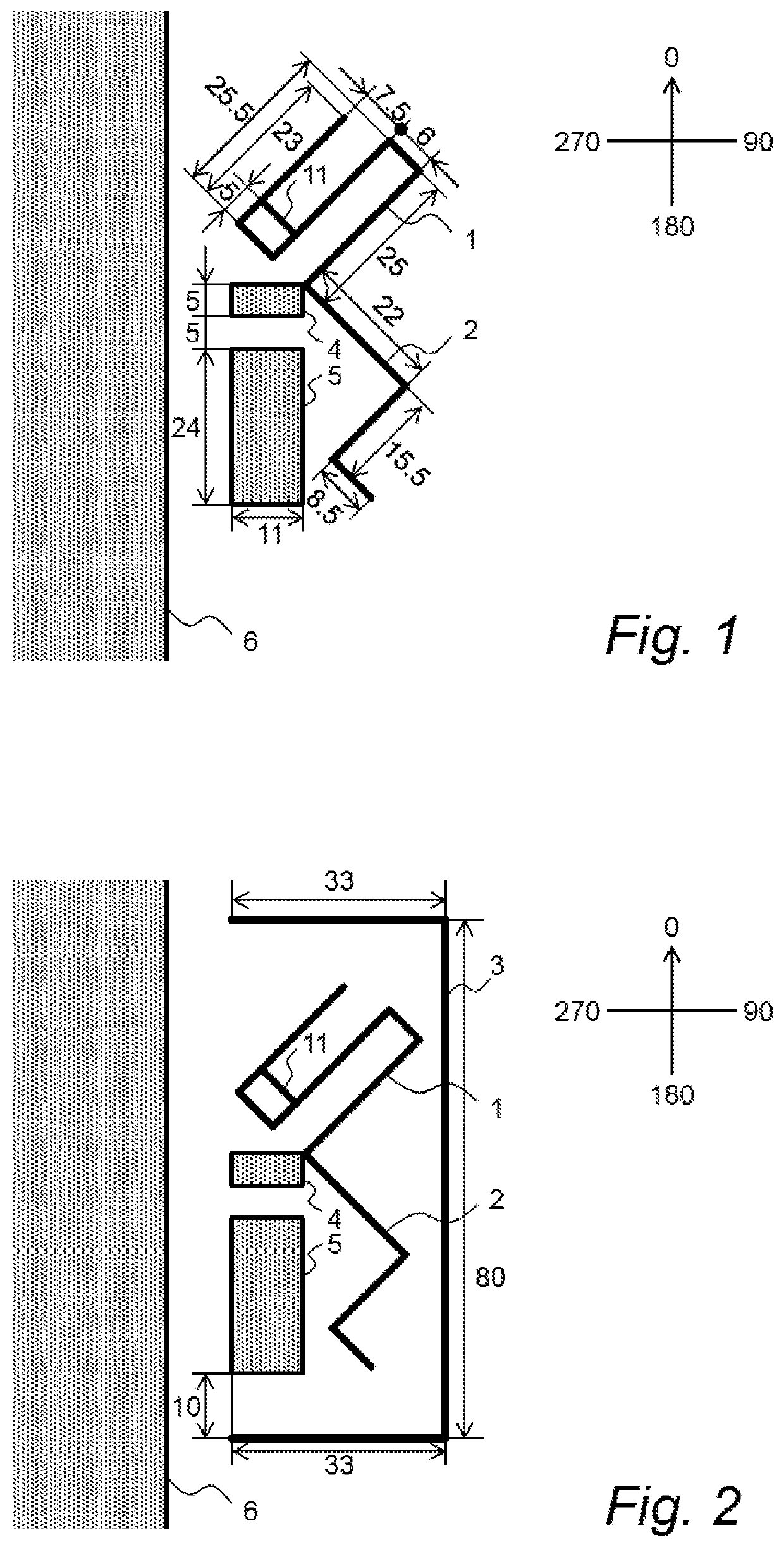
[0020]FIG. 1 is a plan view of a glass antenna according to this invention as viewed from a vehicle interior side.
[0021]The glass antenna having a basic configuration illustrated in FIG. 1 includes a first element 1 and a second element 2 each extending from a core-side power feeding unit 4. In the vicinity of the core-side power feeding unit 4, an earth-side power feeding unit 5 is provided. The core-side power feeding unit 4 and the earth-side power feeding unit 5 are arranged along a body flange 6 of a vehicle.
[0022]The first element 1 extends from the core-side power feeding unit 4 in a direction separated from the body flange 6 (for example, so as to form an angle of 45 degrees with respect to the body flange 6; an angle of 45 degrees in a diagonal direction toward the upper right in FIG. 1, for example) such that an angle of approximately 90 degrees is maintained between the first element 1 and the second element 2. The first element 1 is then bent back, for example, twice to ...
second embodiment
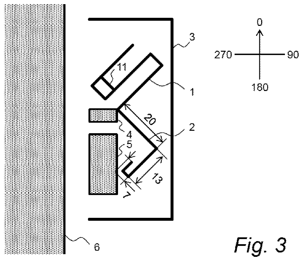
[0039]FIG. 2 is a plan view of a glass antenna according to this invention as viewed from the vehicle interior side.
[0040]The glass antenna illustrated in FIG. 2 is provided with a capacitive element 3 in the antenna of the first embodiment described above. In the second embodiment, the configurations of the first element 1, the second element 2, the core-side power feeding unit 4, and the earth-side power feeding unit 5 are the same as those in the first embodiment described above, and a description thereof is therefore omitted.
[0041]The parasitic element 3 is formed in a U-shape (laterally facing U-shape) open to the left so as to surround the first element 1, the second element 2, the core-side power feeding unit 4, and the earth-side power feeding unit 5. Specifically, an upper line of the parasitic element 3 is provided over the first element 1, a side line of the parasitic element 3 is provided on the right side of the first element 1 and the second element 2, and a lower line...
third embodiment
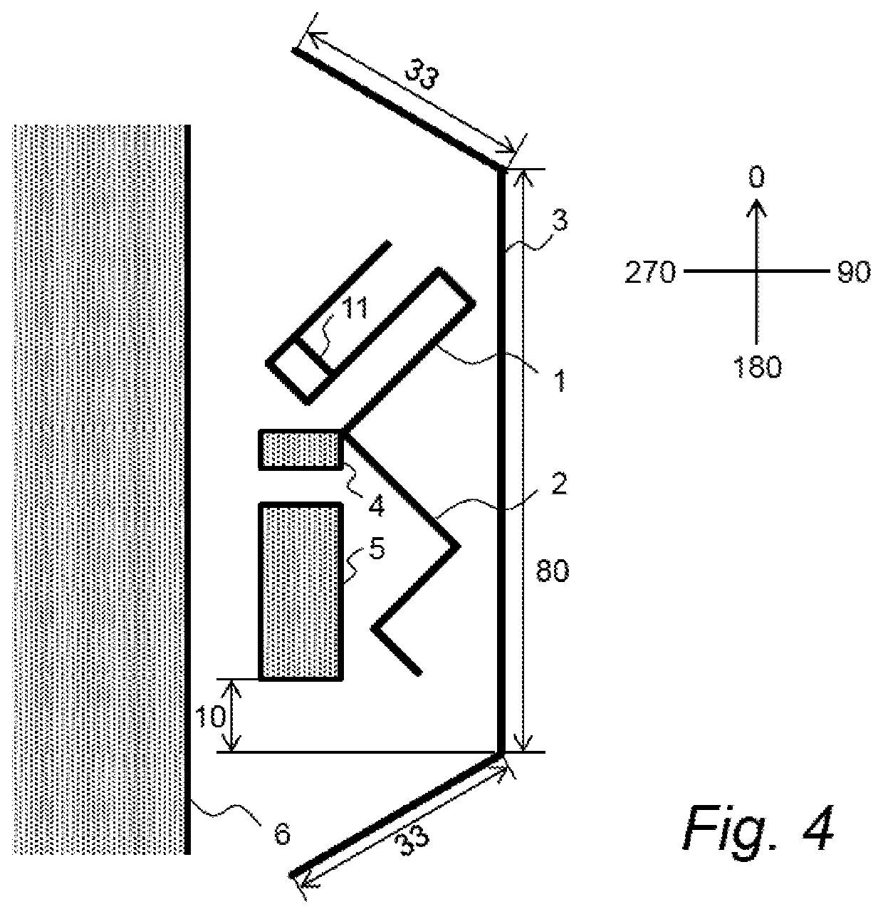
[0044]FIG. 3 is a plan view of a glass antenna according to this invention as viewed from the vehicle interior side.
[0045]The glass antenna illustrated in FIG. 3 is provided with a bending back a leading end of the second element 2 of the antenna of the second embodiment described above. In the third embodiment, the configurations of the first element 1, the parasitic element 3, the core-side power feeding unit 4, and the earth-side power feeding unit 5 are the same as those in the first and second embodiments described above, and a description thereof is therefore omitted.
[0046]The second element 2 extends from the core-side power feeding unit 4 in a direction separated from the first element 1 by 90 degrees to be bent once, and is then bent back to form an element having a length corresponding to about λ / 4, where λ represents the wavelength of the reception frequency.
[0047]In FIG. 3, the length of the second element 2 appropriate for the GPS L1 band (1,575.42 MHz) is illustrated. ...
PUM
 Abstract
Description
Claims
Application Information
 - R&D
- Intellectual Property
- Life Sciences
- Materials
- Tech Scout
- Unparalleled Data Quality
- Higher Quality Content
- 60% Fewer Hallucinations
Browse by: Latest US Patents, China's latest patents, Technical Efficacy Thesaurus, Application Domain, Technology Topic, Popular Technical Reports.
© 2025 PatSnap. All rights reserved.Legal|Privacy policy|Modern Slavery Act Transparency Statement|Sitemap|About US| Contact US: help@patsnap.com


