Inspection apparatus and method for liquid discharge head and liquid discharge head

a liquid discharge head and inspection apparatus technology, applied in other printing apparatus, printing, etc., can solve the problems of failure to determine whether the cause of the discharge error is the cause of the malfunction, the occurrence frequency of malfunctions, and the rupture of the print element, etc., and achieve the effect of simple arrangemen

Active Publication Date: 2017-01-31
CANON KK
View PDF9 Cites 3 Cited by
  • Summary
  • Abstract
  • Description
  • Claims
  • Application Information

AI Technical Summary

Benefits of technology

[0013]One aspect of the present invention provides an inspection apparatus and method for a liquid discharge head which can inspect the quality of an energy generation element or a wire connected to it by a simple arrangement.
[0014]Another aspect of the present invention provides a liquid discharge head which can inspect the quality of an energy generation element or a wire connected to it by a simple arrangement.
[0016]According to an exemplary embodiment of the present invention, the inspection apparatus is connected to the liquid discharge head via a wire and detects the potential change of the upper protection film. It is therefore possible to inspect the liquid discharge head by a simple arrangement without providing a dedicated detection member or detection electrode separately from the liquid discharge head.

Problems solved by technology

Even during actual use after shipment, the occurrence frequency of a malfunction such as a rupture of a print element or disconnection of a wire rises as the use time accumulates.
Out of the above-described inspection methods, print inspection in the inkjet print head can inspect whether discharge is normal or not but cannot determine whether the cause of a discharge error is an electrical failure such as a rupture of a print element or disconnection of a wire, or a fault in an orifice or an ink channel.
If the cause is an electrical failure, ink and time are wasted.
However, since the ON resistance of the ink variously changes in accordance with the amount or distribution of bubbles generated in the ink channel, quality determination may be difficult depending on the obtained voltage waveform.
Since the electrode for detection needs to be provided in the ink tank, the cost of the ink tank becomes high.
In addition, the method of Japanese Patent Laid-Open No. 10-217471 assumes use of conductive ink and is therefore hardly applicable to a general liquid discharge head that does not necessarily discharge a conductive liquid.

Method used


Image

  • Inspection apparatus and method for liquid discharge head and liquid discharge head
  • Inspection apparatus and method for liquid discharge head and liquid discharge head
  • Inspection apparatus and method for liquid discharge head and liquid discharge head

Examples


Embodiment Construction

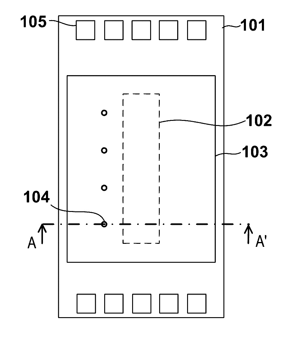
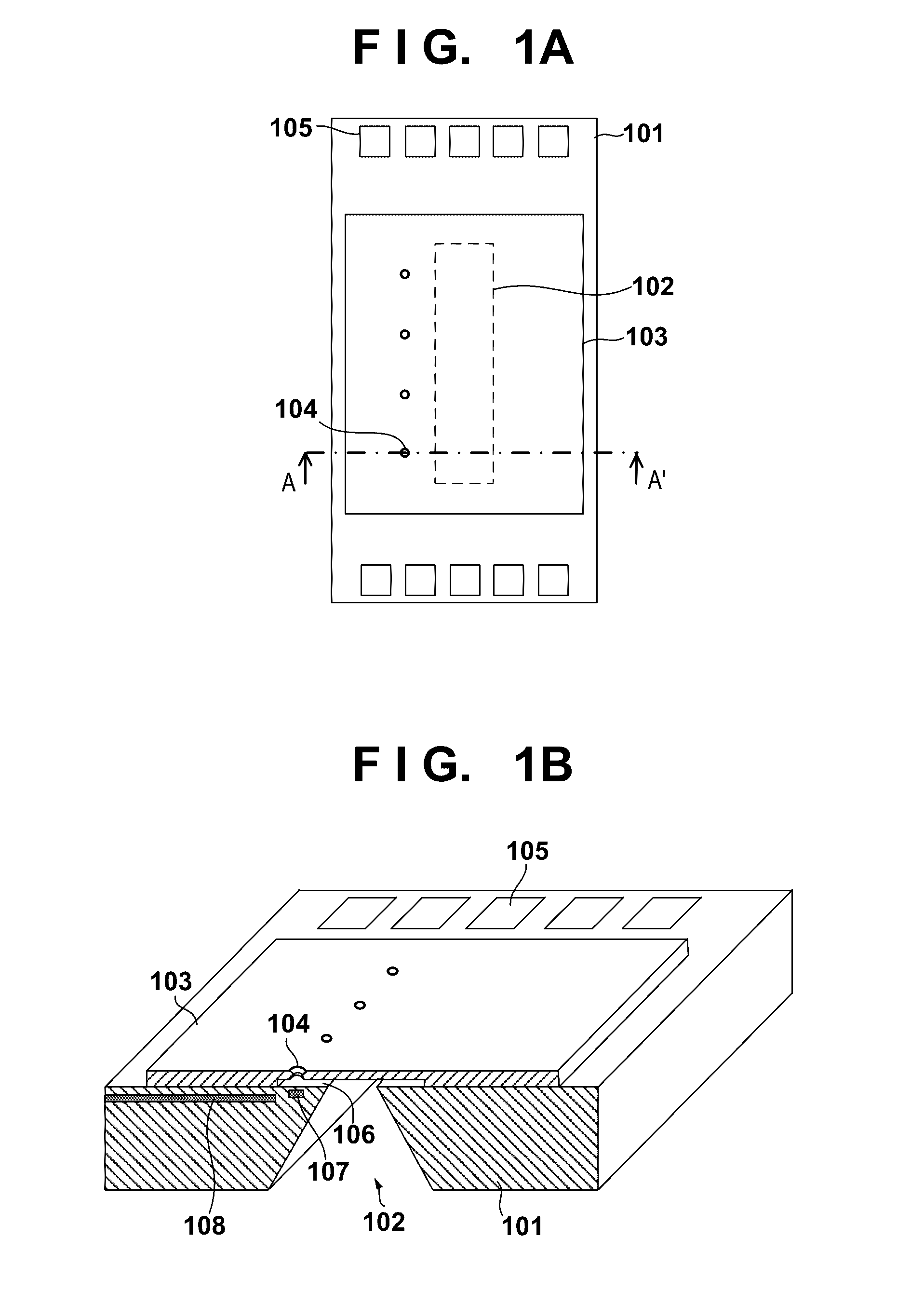
[0032]Preferred embodiments of the present invention will now be described with reference to the accompanying drawings. FIGS. 1A and 1B are views for explaining a liquid discharge head according to the first embodiment of the present invention. FIG. 1A is a plan view, and FIG. 1B is a sectional view taken along a line A-A′ in FIG. 1A. A description will be made here assuming that the liquid discharge head is an inkjet print head that discharges ink as a liquid. Hence, an energy generation element will be referred to as a print element hereinafter. The liquid discharge head to which the present invention is applied is not limited to the inkjet print head.

[0033]An orifice forming member 103 is arranged on one surface (the upper surface shown in FIGS. 1A and 1B) of an element substrate 101 made of silicon or the like. Orifices 104 to discharge a liquid are arrayed at a predetermined interval in the orifice forming member 103. Here, four orifices 104 are arranged in a line at a predeter...


PUM


Abstract

An apparatus for inspecting a liquid discharge head including an energy generation element provided on an element substrate and configured to make energy act on a liquid to discharge the liquid from an orifice, a lower protection film having an electrical insulating property and provided on the element substrate while covering the energy generation element, a wiring layer provided between the element substrate and the lower protection film and configured to supply electrical signal for driving to the energy generation element, and a conductive upper protection film provided on the lower protection film is provided. The apparatus comprises a detection circuit configured to detect a potential of the upper protection film when the energy generation element is driven; and a determination circuit configured to determine a driving state of the energy generation element from information about the potential detected by the detection circuit.

Description

BACKGROUND OF THE INVENTION[0001]Field of the Invention[0002]The present invention relates to a liquid discharge head that discharges a liquid from an orifice by making energy act on the liquid. In particular, the present invention relates to an inspection apparatus and method for inspecting the quality of driving of an energy generation element that is provided on the liquid discharge head and generates energy to discharge the liquid, and a liquid discharge head suitable for the inspection method.[0003]Description of the Related Art[0004]A liquid discharge head makes energy act on a liquid existing in a fluid channel and thus discharges the liquid from an orifice. To make energy act on the liquid in the fluid channel, an energy generation element is often provided in the vicinity of the fluid channel. The energy generation element is generally formed on one surface of a substrate made of, for example, silicon. The energy generation element is in contact with the liquid via a protec...

Claims


Application Information

Patent Timeline
Patent Type & Authority Patents(United States)
IPC IPC(8): B41J29/393
CPCB41J29/393B41J2/04555B41J2/04561B41J2/04576B41J2/04588
Inventor KANNO, HIDEO
Owner CANON KK
Why Eureka
Try Eureka