Aircraft electric braking system

a technology of electric braking and aircraft, which is applied in the direction of braking systems, aircraft braking arrangements, braking components, etc., can solve problems such as partial or full loss of braking control

Active Publication Date: 2017-01-31
AIRBUS OPERATIONS LTD
View PDF50 Cites 3 Cited by
  • Summary
  • Abstract
  • Description
  • Claims
  • Application Information

AI Technical Summary

Benefits of technology

[0013]The first motor controller and the second motor controller may include similar hardware for generating a pulse-width modulation signal. Alternatively, the first motor controller and the second motor controller may include dissimilar hardware for generating a pulse-width modulation signal so as to provide protection against common mode failure of the first and second motor controllers.

Problems solved by technology

There is a therefore a potential for simultaneous failure of several EMACs leading to partial or full loss of braking control, which is undesirable.

Method used


Image

  • Aircraft electric braking system
  • Aircraft electric braking system
  • Aircraft electric braking system

Examples


Embodiment Construction

)

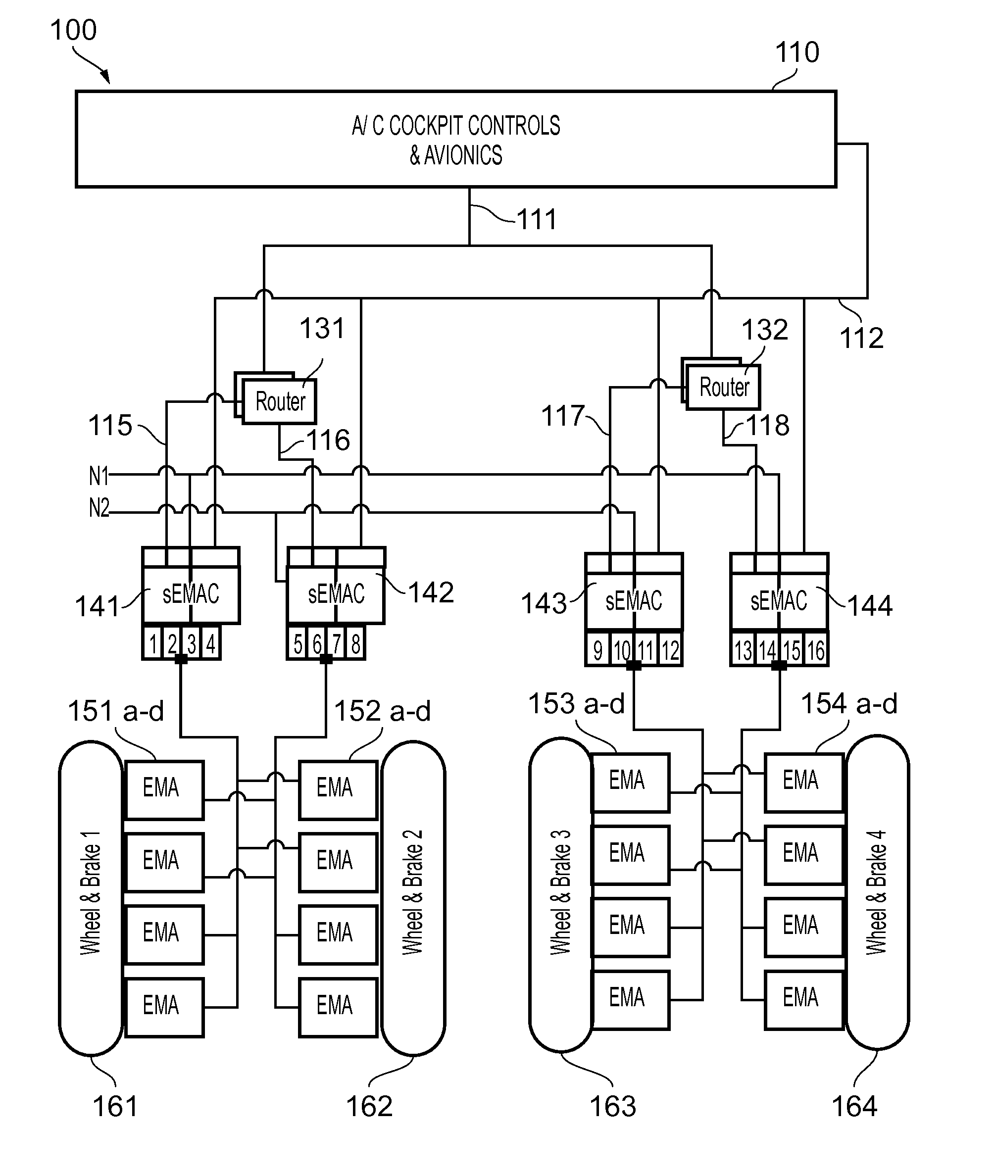
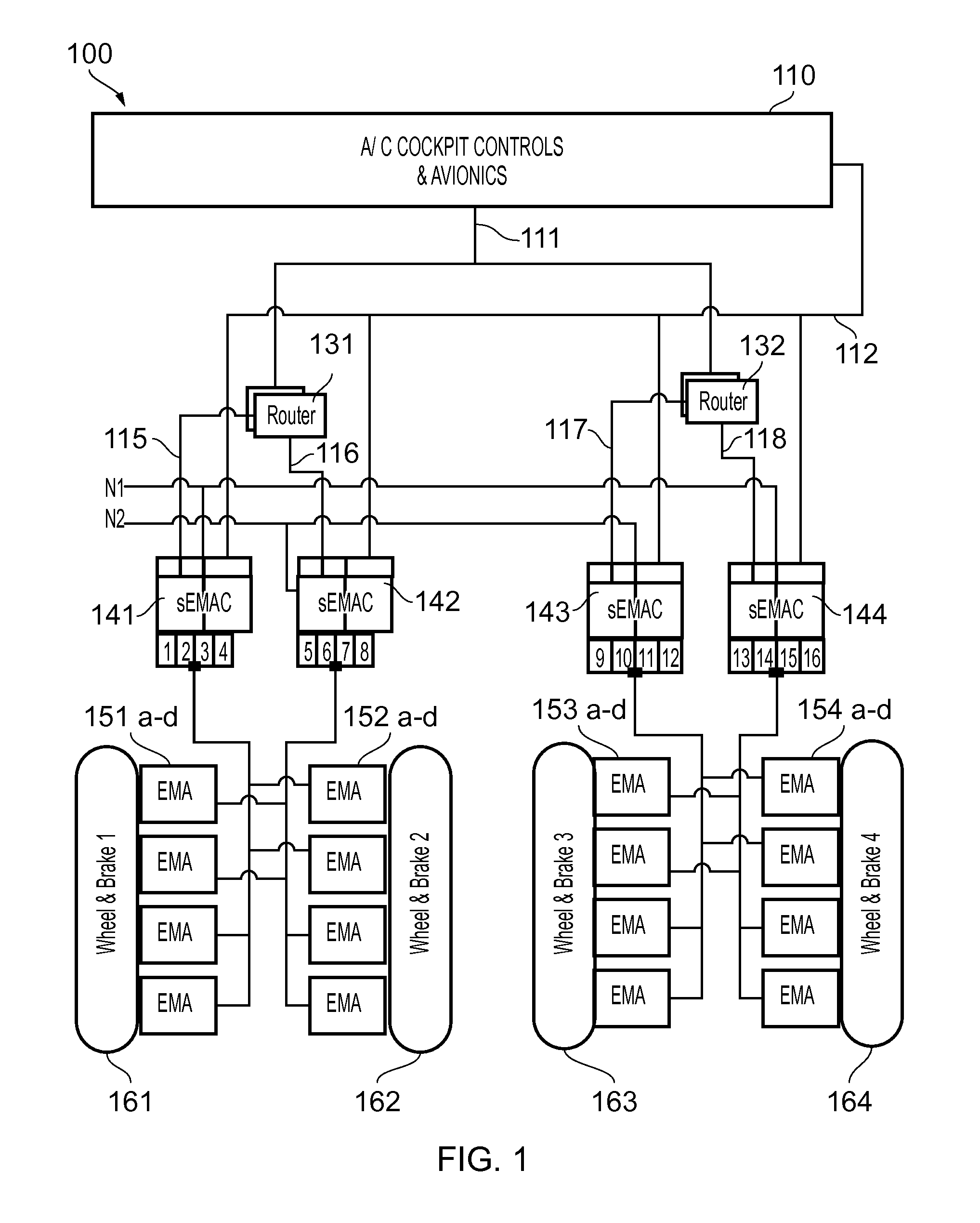
[0035]The electrically actuated aircraft braking system 100 of the first embodiment shown in FIG. 1 is configured for an aircraft having two braked main landing gears, one on either side of the aircraft centre line. However, it will be appreciated that the invention described herein relates to any aircraft configuration having braking wheels, including aircraft with more than two main landing gears and / or braked nose landing gear. The braking system 100 features (partially) distributed avionics.

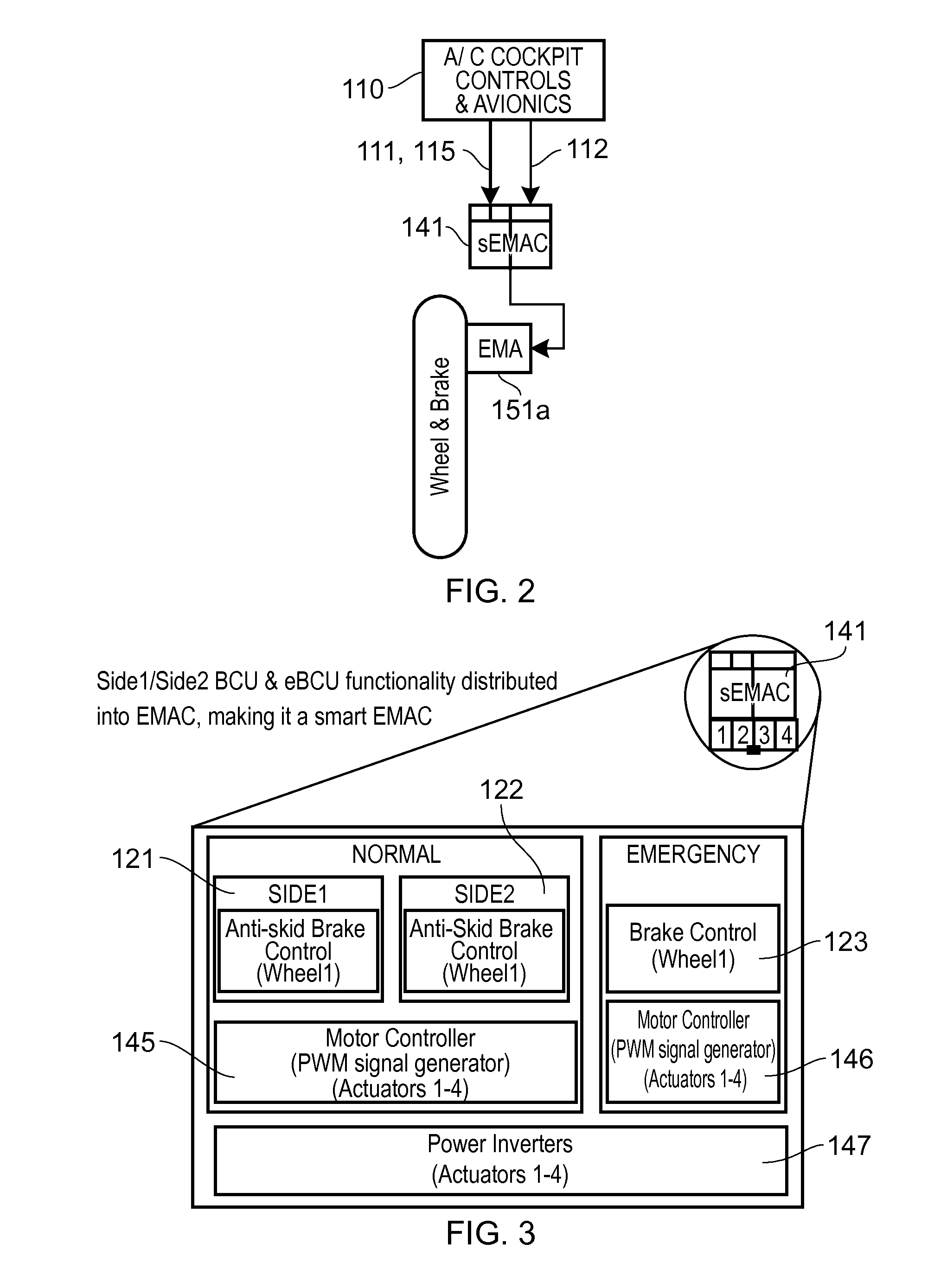
[0036]As best shown in FIG. 3 the braking system 100 comprises both a normal and an emergency system. The normal system includes dual redundant brake control units (BCUs) 121, 122 assigned to particular sides, e.g. aircraft avionics network or electrical power network sides (side1, side2, etc.). The emergency system includes an emergency BCU (eBCU) 123. The eBCU 123 provides protection against loss of function of both BCUs 121, 122, e.g. from failure of the BCUs, failure of the A / C avionics,...


PUM


Abstract

An electrically actuated braking system for an aircraft. The system includes: an electro-mechanical brake actuator (EMAbrake) proximate a wheel of the aircraft, the EMAbrake including a motor; an electro-mechanical actuator controller (EMAC) including a motor controller for generating a drive signal for the EMAbrake; a braking control unit (BCU) for generating a braking force command signal for the EMAC during a normal mode of operation; and an emergency braking control unit (eBCU) for generating a braking force command signal for the EMAC during an emergency operating mode. The eBCU is disposed together with the EMAC in a common line replaceable unit (LRU).

Description

CROSS-REFERENCE TO RELATED APPLICATION[0001]This application claims priority to GB Application No. 1320939.0, filed 27 Nov. 2013, the entire content of which is hereby incorporated by reference.FIELD OF THE INVENTION[0002]The present invention relates to an electrically actuated braking system for an aircraft.BACKGROUND OF THE INVENTION[0003]Electric systems are gradually replacing hydraulic systems on many commercial, and military, aircraft. Current “brake by wire” aircraft systems may have a generally centralised architecture in which pilot inputs are interpreted and command and monitoring signals are communicated via a databus and as analogue / discrete signals to a brake control unit (BCU). An exemplary centralised architecture is described in US 2008 / 0030069 A1.[0004]The BCU interprets the commands from the aircraft cockpit controls and avionics and calculates braking force commands for each actuated landing gear wheel of the aircraft. This may include fast loop anti-skid control...

Claims


Application Information

Patent Timeline
Patent Type & Authority Patents(United States)
IPC IPC(8): B60T8/17B64C25/44B64C25/46B60T8/88B60T8/176
CPCB60T8/1703B60T8/17B60T8/176B60T8/885B64C25/44B64C25/46B60T2270/402B60T8/325B60T13/741B60T2270/404
Inventor IORDANIDIS, GEORGEREES, JOHN
Owner AIRBUS OPERATIONS LTD
Why Eureka
Try Eureka