Aircraft braking system architecture

Pending Publication Date: 2020-04-02
SAFRAN LANDING SYST
View PDF1 Cites 0 Cited by
  • Summary
  • Abstract
  • Description
  • Claims
  • Application Information

AI Technical Summary

Benefits of technology

[0014]An object of the invention is an aircraft braking system architecture that

Problems solved by technology

However, this level of redundancy may be ineffective faced with a common mode fault resulting from the simultaneous failure of all the components of the same type, for example from the hardware failure of all the microcontrollers of the control channel or of the power module, or resulting from an error leading for example to an error by the software hosted by the microcontrollers under conditions not provided for at the development stage.
avoiding the introduction of inactive components into the normal operation of the electrical braking system (potentiall

Method used


Image

  • Aircraft braking system architecture
  • Aircraft braking system architecture
  • Aircraft braking system architecture

Examples


first embodiment

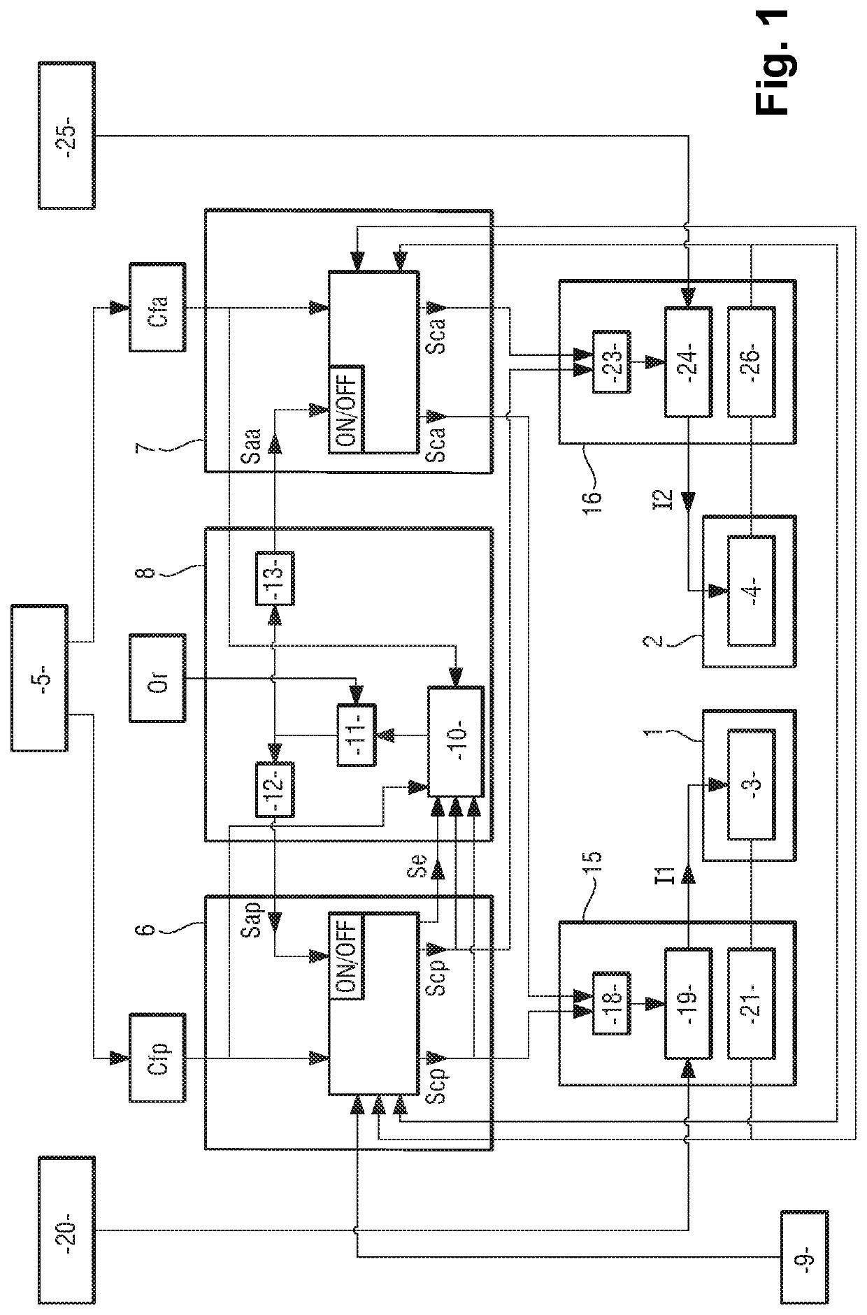
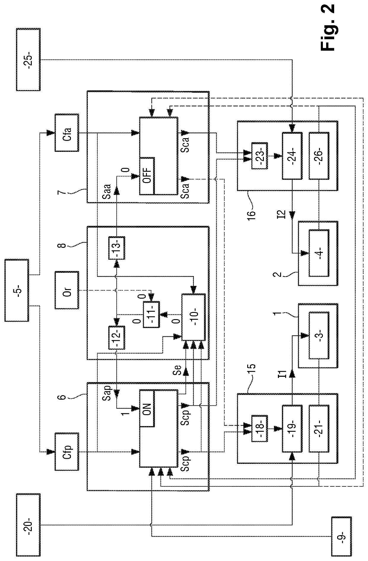
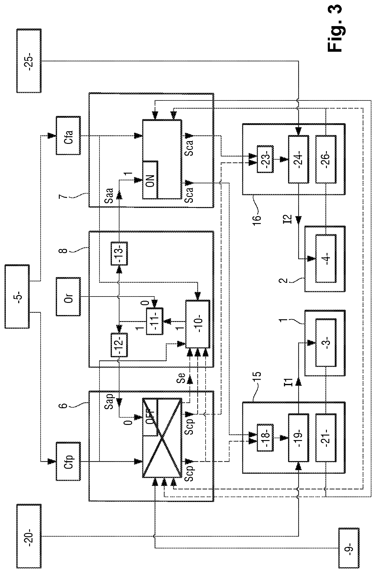
[0034]Referring to FIG. 1, the braking system architecture in accordance with the invention comprises a brake intended to brake a so-called “braked” wheel of a landing gear of the aircraft. The brake comprises friction members, for example a stack of carbon disks, and a first electromechanical actuator 1 and a second electromechanical actuator 2 that are adapted to apply a braking force to the friction members. The first electromechanical actuator 1 comprises a first electric motor 3 and the second electromechanical actuator 2 comprises a second electric motor 4.

[0035]The first electric motor 3 and the second electric motor 4 are controlled by a braking order generated for example by a pilot of the aircraft 5 or by an automatic braking system. The braking order is transformed into a principal braking command Cfp and an alternative braking command Cfa that represent the braking order and are generated via different mechanisms in order to prevent common mode faults between these two c...

third embodiment

[0100]A braking architecture in accordance with the invention is described next with reference to FIG. 6.

[0101]The surveillance unit 208 again comprises a surveillance module 210, an OR gate 211, a NOT gate 212 and a timer 213.

[0102]The surveillance module 210 has a first input via which it receives the principal control signals Scp produced by the principal control channel 206 and sent to the first electromechanical actuator 201, a second input via which it receives the principal control signals Scp produced by the principal control channel 206 and sent to the second electromechanical actuator 202, a third input via which it receives the state signal Se produced by the principal control channel 106, a fourth input via which it receives the principal braking command Cfp, a fifth input via which it receives the alternative control signals Sca produced by the alternative control channel 207 and sent to the first electromechanical actuator 201, a sixth input via which it receives the a...


PUM


Abstract

Aircraft braking system architecture comprising:
    • a brake comprising electromechanical actuators (1, 2);
    • a principal control channel (6) and an alternative control channel (7) comprising electrical components that are at least partly different and adapted to provide respectively a principal braking control function and an alternative braking control function that are at least partly different;
    • power modules (15, 16) comprising electrical components that are at least partly different and adapted to generate electrical power supply currents (I1, I2) on the basis of principal control signals or alternative control signals;
    • a surveillance unit (8) adapted to ensure that in normal operation the principal control signals are used and that in the event of a fault the alternative control signals are used to generate the electrical power supply currents.

Description

[0001]The invention concerns the field of aircraft braking system architectures.BACKGROUND OF THE INVENTION[0002]An aircraft electrical braking system architecture conventionally comprises a plurality of brakes each intended to brake one wheel of a landing gear of the aircraft.[0003]Each brake comprises friction members and independent electromechanical actuators (typically four actuators) intended to apply a braking force to the friction members and thus to exert a braking torque on the wheel.[0004]The architecture also comprises a control channel that receives a braking command from the pilot and transforms the braking command into control signals and a power module that generates from the control signals electrical power supply currents for supplying power to the electric motors of the electromechanical actuators.[0005]An architecture of this kind naturally and intrinsically has a high level of redundancy by virtue of the number of independent electromechanical actuators used for...

Claims


Application Information

Patent Timeline
IPC IPC(8): B60T8/17B60T8/175B60T8/176B64C25/46
CPCB60T8/1703B60T2270/403B60T8/176B64C25/46B60T8/175B60T2270/20B60T2270/402B60T2270/10B64C25/44B60T13/741B60T8/885B64C25/42B60T2270/406
Inventor ONFROY, DOMINIQUEFREY, OLIVIERGOYEZ, BRIAN
Owner SAFRAN LANDING SYST
Why Eureka
Try Eureka