Aircraft electric braking system

a technology of electric braking and aircraft, which is applied in the direction of braking systems, aircraft braking arrangements, braking components, etc., can solve problems such as partial or full loss of braking control

Active Publication Date: 2019-04-16
AIRBUS OPERATIONS LTD
View PDF60 Cites 1 Cited by
  • Summary
  • Abstract
  • Description
  • Claims
  • Application Information

AI Technical Summary

Benefits of technology

[0008]The invention is advantageous in that the common LRU enables reduced wiring complexity to the EMAbrake, providing weight and cost savings and enhanced reliability compared to previous electrically actuated braking systems.
[0014]The first motor controller and the second motor controller may include similar hardware for generating a pulse-width modulation signal. Alternatively, the first motor controller and the second motor controller may include dissimilar hardware for generating a pulse-width modulation signal so as to provide protection against common mode failure of the first and second motor controllers.

Problems solved by technology

There is a therefore a potential for simultaneous failure of several EMACs leading to partial or full loss of braking control, which is undesirable.

Method used


Image

  • Aircraft electric braking system
  • Aircraft electric braking system
  • Aircraft electric braking system

Examples


first embodiment

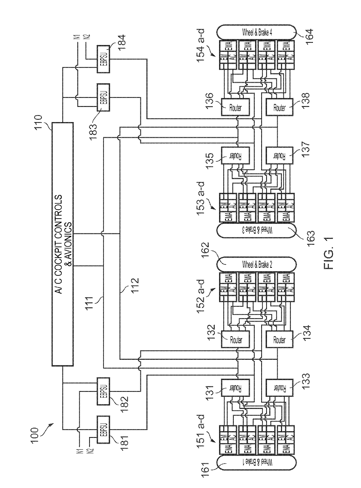
[0045]The electrically actuated aircraft braking system 100 of the first embodiment shown in FIG. 1 is configured for an aircraft having two braked main landing gears, one on either side of the aircraft center line. However, it will be appreciated that the invention described herein relates to any aircraft configuration having braking wheels, including aircraft with more than two main landing gears and / or braked nose landing gear. The braking system 100 features fully distributed avionics.

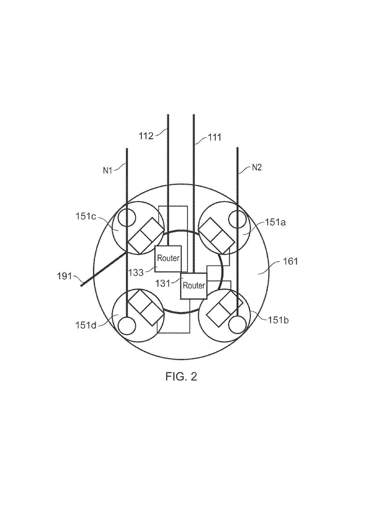
[0046]The braking system 100 includes aircraft cockpit controls and aircraft avionics 110 which communicates via databuses 111, 112 and routers 131-138 with “fully smart” electro-mechanical brake actuators (EMAs) 151a-d, 152a-d, 153a-d, and 154a-d (described in detail below) associated with wheel and brake groups 161-164. In this example there are four wheel and brake groups (one per wheel of two diablo main landing gears), and four fully smart EMAs per wheel and brake group. Electric brake power s...

second embodiment

[0079]FIG. 9 illustrates a schematic of the control of a single fully smart EMA 251a of a fully distributed electrically actuated aircraft braking system architecture.

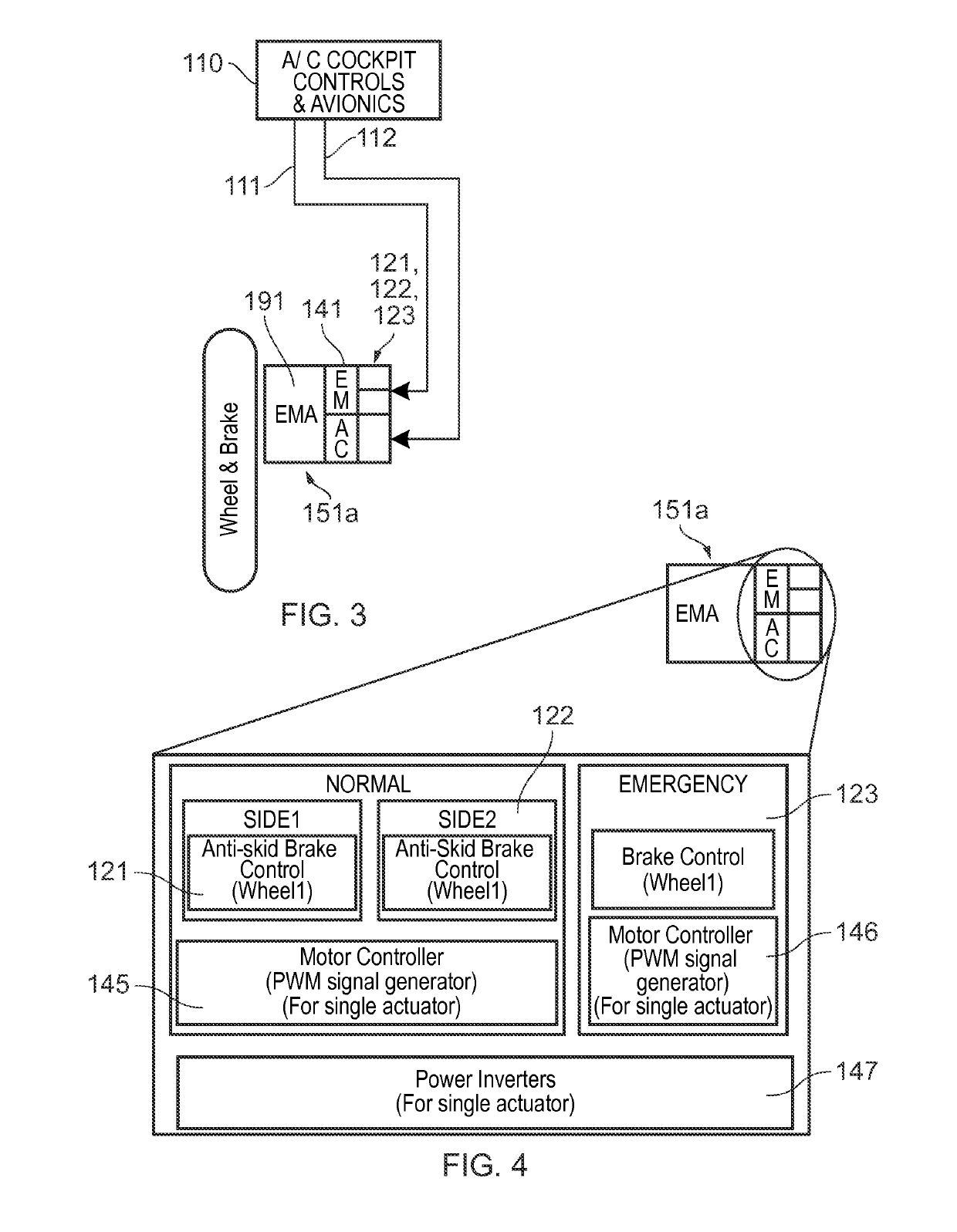
[0080]The braking system of the second embodiment shares many similarities with the first embodiment of FIGS. 1-8 and includes the following key difference. In place of the fully smart EMAs in which the normal and emergency BCU functionality is packaged within the fully smart EMA in a single line replaceable unit (LRU), the fully smart EMA 251a has only the (normal) side 1 and side 2 BCU 221, 222 functionality incorporated in the LRU whilst the emergency BCU (eBCU) LRU 223 remains separate and remote from the fully smart EMA 251a.

[0081]The fully smart EMA may be adopted in the architecture of FIG. 1 with suitable modifications to incorporate the additional eBCU LRU 223. Either a single eBCU LRU may be provided electrically connected to each of the fully smart EMAs, or to a group of the fully smart EMAs; or a plurality...

third embodiment

[0083]FIG. 11 illustrates a schematic of the control of a single fully smart EMA 351a of a fully distributed electrically actuated aircraft braking system architecture.

[0084]The braking system of the third embodiment shares many similarities with the first embodiment of FIGS. 1-8 and includes the following key difference. In place of the fully smart EMAs in which the normal and emergency BCU functionality is packaged within the fully smart EMA in a single line replaceable unit (LRU), the fully smart EMA 351a has only the emergency BCU(eBCU) 323 functionality incorporated in the LRU whilst the (normal) side 1 and side 2 BCU 321, 322 LRUs remain separate and remote from the fully smart EMA 351a.

[0085]The fully smart EMA may be adopted in the architecture of FIG. 1 with suitable modifications to incorporate the additional BCU LRUs 221, 222. Side 1 and side 2 BCU LRUs may be provided electrically connected to each of the fully smart EMAs, or to a group of the fully smart EMAs; or a plu...


PUM


Abstract

An electrically actuated braking system for an aircraft, comprising: an electro-mechanical brake actuator (EMAbrake) proximate a wheel of the aircraft, the EMAbrake including a motor; an electro-mechanical actuator controller (EMAC) including a motor controller for generating a drive signal for the EMAbrake; and a braking control unit for generating a braking force command signal for the EMAC, wherein the braking control unit and the EMAC are disposed together with the EMAbrake in a common line replaceable unit (LRU).

Description

CROSS-REFERENCE TO RELATED APPLICATION[0001]This application claims priority to GB Application No. 1320941.6, filed 27 Nov. 2013, the entire content of which is hereby incorporated by reference.FIELD OF THE INVENTION[0002]The present invention relates to an electrically actuated braking system for an aircraft.BACKGROUND OF THE INVENTION[0003]Electric systems are gradually replacing hydraulic systems on many commercial, and military, aircraft. Current “brake by wire” aircraft systems may have a generally centralized architecture in which pilot inputs are interpreted and command and monitoring signals are communicated via a databus and as analogue / discrete signals to a brake control unit (BCU). An exemplary centralized architecture is described in US 2008 / 0030069 A1.[0004]The BCU interprets the commands from the aircraft cockpit controls and avionics and calculates braking force commands for each actuated landing gear wheel of the aircraft. This may include fast loop anti-skid control...

Claims


Application Information

Patent Timeline
Patent Type & Authority Patents(United States)
IPC IPC(8): B64C25/44B64C25/46B60T8/17
CPCB64C25/44B64C25/46B60T8/1703B60T2270/413B60T8/325B60T13/741B60T2270/404
Inventor IORDANIDIS, GEORGEREES, JOHN
Owner AIRBUS OPERATIONS LTD
Why Eureka
Try Eureka