Circuit structure and working method of mechanical-electric integrated device

A technology of circuit structure and working method, applied in the direction of electrical program control, program control in sequence/logic controller, etc., can solve the problems of mixed wiring, difficult long-distance wiring, troublesome operability, etc.

Inactive Publication Date: 2018-01-05
常州佳畅智能科技有限公司
View PDF0 Cites 0 Cited by
  • Summary
  • Abstract
  • Description
  • Claims
  • Application Information

AI Technical Summary

Problems solved by technology

Therefore, in complex distributed control systems, the complexity and reliability of wiring becomes very prominent. In traditional methods, each external signal usually requires a wire to be pulled from one place (such as the main control box) to another place. [Such as on-site], if a system has hundreds or even thousands of signals, it will definitely bring great difficulties to long-distance wiring
For example, in the embroidery machine, pattern machine and shoe upper machine system, the signa

Method used


Image

  • Circuit structure and working method of mechanical-electric integrated device
  • Circuit structure and working method of mechanical-electric integrated device

Examples


Example Embodiment

[0020] Example 1

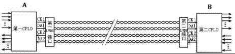
[0021] refer to figure 1 ,like figure 1 The circuit structure of a kind of mechanical and electrical integration equipment shown, comprises first CPLD, second CPLD, first low-voltage differential signal LVDS interface, second low-voltage differential signal LVDS interface, clock and data line; Said first CPLD electrical property connected to the first low-voltage differential signal LVDS interface; the second CPLD is electrically connected to the second low-voltage differential signal LVDS interface; the first low-voltage differential signal LVDS interface and the second low-voltage differential signal LVDS interface are electrically connected through the clock line and the data line connect.

Example Embodiment

[0022] Example 2

[0023] refer to figure 2 ,like figure 2 The working method of the circuit structure of a kind of mechatronics equipment shown, comprises the following steps:

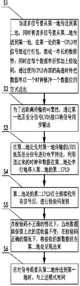
[0024] S1, when many signals are to be transmitted from the first ground to the second ground, and many signals are to be transmitted from the second ground to the first ground at the same time, the first CPLD at the first place packs the signal groups to form a long string Data string; at the same time, add a check code at the end of each data string, and send the data string in the form of a clock pulse and a data bit by using the high-speed clock inside the CPLD;

[0025] S2, for the reliability of long-distance transmission, synchronously output the signal through the first low-voltage differential signal LVDS interface;

[0026] S3, at the second location, first perform level conversion on the LVDS low-voltage differential signal transmitted at the first location, and use the clock and data ...


PUM


Abstract

The invention discloses a circuit structure and working method of an electromechanical integration device. The circuit structure includes a first CPLD, a second CPLD, a first low-voltage differential signal LVDS interface, a second low-voltage differential signal LVDS interface, a clock and Data line; the first CPLD is electrically connected to the first low-voltage differential signal LVDS interface; the second CPLD is electrically connected to the second low-voltage differential signal LVDS interface; the first low-voltage differential signal LVDS interface and the second low-voltage differential signal The LVDS interface is electrically connected through a clock line and a data line. The present invention utilizes LVDS technology to realize a small amount of 8 wires, pack and unpack data through CPLD integration technology, to transmit a large number of signals in two places separated by a certain distance, to reduce wiring complexity in mechatronics and other equipment, and at the same time It has a significant effect on the reliability of the system and reduces the troubleshooting time.

Description

technical field [0001] The invention relates to a circuit structure, in particular to a circuit structure and working method of an electromechanical integration device. Background technique [0002] With the increase of labor costs, the required automatic processing equipment is more and more complex, and with the popularization of embedded computer control, distributed control has become an inevitable trend. Therefore, in complex distributed control systems, the complexity and reliability of wiring becomes very prominent. In traditional methods, each external signal usually requires a wire to be pulled from one place (such as the main control box) to another place. [Such as on-site], if a system has hundreds or even thousands of signals, this will definitely bring great difficulties to long-distance wiring. For example, in the embroidery machine, pattern machine and shoe upper machine system, the signals arranged on site include: machine head signal, frame four-way offside...

Claims


Application Information

Patent Timeline
IPC IPC(8): G05B19/05
Inventor 周小玉
Owner 常州佳畅智能科技有限公司
Why Eureka
Try Eureka