
A radio frequency circuit and electronic equipment

A radio frequency circuit and radio frequency front-end technology, applied in the field of communication, can solve problems such as complex radio frequency circuit wiring, and achieve the effect of reducing the number and complexity of wiring

Active Publication Date: 2016-09-28
LENOVO (BEIJING) LTD
View PDF7 Cites 0 Cited by
  • Summary
  • Abstract
  • Description
  • Claims
  • Application Information

AI Technical Summary

Problems solved by technology

[0019] Embodiments of the present invention provide a radio frequency circuit and electronic equipment, which are used to solve the technical problem of complex wiring of radio frequency circuits existing in the prior art

Method used


Image

  • A radio frequency circuit and electronic equipment
  • A radio frequency circuit and electronic equipment
  • A radio frequency circuit and electronic equipment

Examples


Embodiment 1

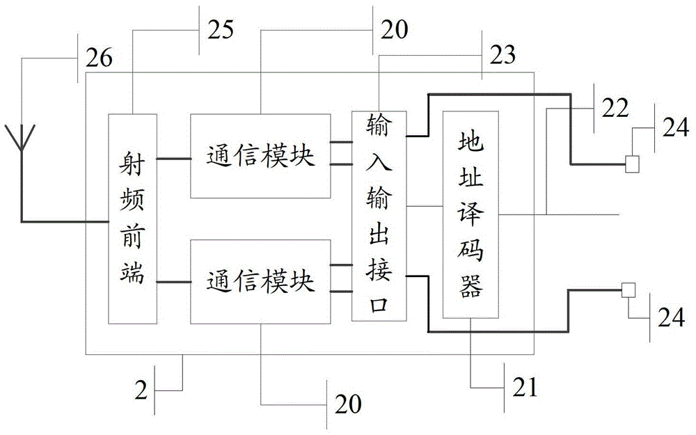
[0072] In this embodiment, the radio frequency chip is introduced by taking N communication modules as a wireless local area network module and a bluetooth module as an example.

[0073] Please refer to Figure 4 , the radio frequency chip specifically includes the following structure:

[0074] Wireless local area network module 40a, for carrying out data transmission by wireless local area network;

[0075] The bluetooth module 40b is used for carrying out data transmission through the bluetooth protocol;

[0076] The input and output interface 41 is connected to the wireless local area network module 40a and the bluetooth module 41b;

[0077] Address decoder 42 is connected with wireless local area network module 40a and bluetooth module 40b through input and output interface 41;

[0078] Configuration bus 43, connected to address decoder 42;

[0079] The first data transmission interface 44 is connected to the wireless local area network module 40a through the input and...

Embodiment 2

[0089] In this embodiment, the radio frequency chip is introduced by taking the N communication modules as a wireless local area network module, a bluetooth module and an FM radio module as an example.

[0090] Please refer to Figure 5 , the radio frequency circuit specifically includes the following structure:

[0091] Wireless local area network module 50a, for carrying out data transmission by wireless local area network;

[0092] The bluetooth module 50b is used for carrying out data transmission through the bluetooth protocol;

[0093] FM broadcasting module 50c, for receiving data by FM broadcasting;

[0094] The radio frequency front end 51 is connected with the wireless local area network module 50a and the bluetooth module 50b;

[0095] The first antenna 52a is connected with the wireless local area network module 50a and the bluetooth module 50b through the radio frequency front end 51;

[0096] The second antenna 52b is connected to the FM radio module 50c;

...


PUM


Abstract

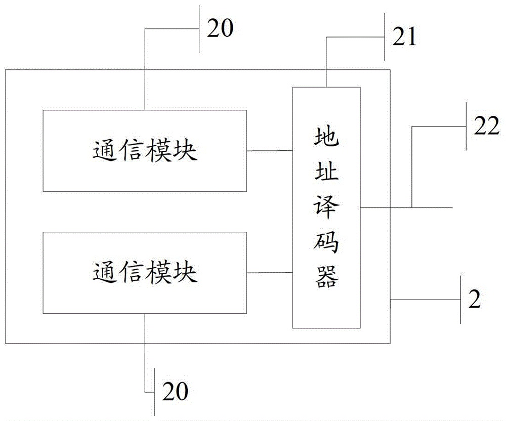
The invention relates to the field of a communication technology and discloses a radio frequency circuit and electronic equipment, aiming to solve the technical problem in the prior art that the radio frequency circuit has complicated wire arrangement. The radio frequency circuit comprises N communication modules, an address decoder and a configuration bus, wherein the address decoder is connected with the N communication modules; the configuration bus is connected with the address decoder; a first configuration parameter is sent to the address decoder after the configuration bus obtains the first configuration parameter, so that first address information is obtained, and the first communication module corresponding to the first address information is determined from the N communication modules; then the first configuration parameter is sent to the first communication module and is used for carrying out parameter setting on the first communication module by the first configuration parameter. Namely, the parameter setting of at least two communication modules can be realized by using only one configuration bus, so that the quantity of the configuration bus is reduced, and the technical effect of the wire arrangement complexity of the radio frequency circuit is achieved.

Description

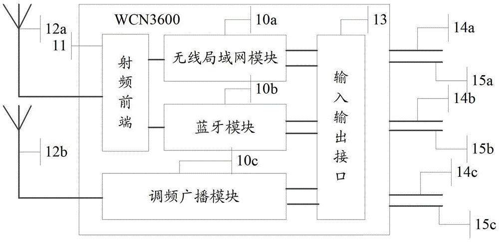
technical field [0001] The invention relates to the technical field of communication, in particular to a radio frequency circuit and electronic equipment. Background technique [0002] With the continuous development of science and technology, electronic technology has also been developed rapidly, and more and more electronic devices have been produced, such as mobile phones, tablet computers, notebook computers and so on. These electronic devices have increasingly powerful functions and have become an indispensable part of people's lives. [0003] Many electronic devices have communication functions, and can receive or send data. In order to realize the communication function, these electronic devices are equipped with radio frequency circuits, such as figure 1 This is a schematic diagram of a radio frequency circuit, specifically including: [0004] A wireless local area network (WLAN: Wireless Local Area Networks) module 10a, used for data transmission through the wirel...

Claims


Application Information

Patent Timeline
Patent Type & Authority Patents(China)
IPC IPC(8): H04B1/40
Inventor 单文英
Owner LENOVO (BEIJING) LTD
Learn More