Electromechanical actuator with dual excitation

a technology of electric motor and actuator, which is applied in the direction of mechanical equipment, mechanical energy handling, transportation and packaging, etc., can solve the problems of high cost, large failure, and compromise the ability of aircraft to brake, and achieve the effect of reducing the risk of a common mode failur

Active Publication Date: 2014-09-23
SAFRAN LANDING SYSTEMS
View PDF12 Cites 5 Cited by
  • Summary
  • Abstract
  • Description
  • Claims
  • Application Information

AI Technical Summary

Benefits of technology

[0011]An object of the invention is to propose an actuator that makes it possible to reduce the risk of a common mode failure, while avoiding the need to develop two distinct types of actuator.SUMMARY OF THE INVENTION
[0020]Thus, the braking actuator of the invention makes it possible to reduce the risk of a malfunction of the braking function since it provides:
[0023]Thus, the actuator of the invention can continue to function and control the movement of the movable pusher:
[0026]This arrangement makes it possible to establish operation that is much more reliable. It suffices to ensure that the power supplies to the two exciters and the power supplies to the two transmitters are distinct (internal and / or external relative to the actuator). Thus, a common failure of the first exciter in all or some of the actuators can easily be compensated by using the second exciter. This reduces the risk that a failure affecting the first exciters will disturb the power supply to the second exciters, since the power supply to the second exciters is not connected to the first exciters. The same applies to the transmitters of the position sensor. A common breakdown of the first transmitters will not prevent the second transmitters being used, and therefore will not prevent a signal representative of the position of the movable portion relative to the stationary portion being provided, as is necessary in order to control the motor.
[0031]Provision may also be made for the transmitters to be powered simultaneously in order to improve the accuracy with which the position of the movable portion is measured relative to the stationary portion.
[0032]The invention thus makes it possible to improve the availability of the function for actuating an aircraft brake.

Problems solved by technology

Unfortunately, in the event of a failure of one of the components of the actuator or of its control means, there is a risk of the failure being common to a plurality of actuators and leading to a massive failure that compromises the ability of the aircraft to brake.
Nevertheless, such a solution is very expensive since it requires two types of actuator to be developed and requires distinct sets of parts to be managed.

Method used


Image

  • Electromechanical actuator with dual excitation
  • Electromechanical actuator with dual excitation
  • Electromechanical actuator with dual excitation

Examples


Embodiment Construction

[0039]The invention is shown and described in detail herein in an application to a brake of a fuselage undercarriage. Naturally, such an application is not limiting and the invention may be applied to other undercarriages.

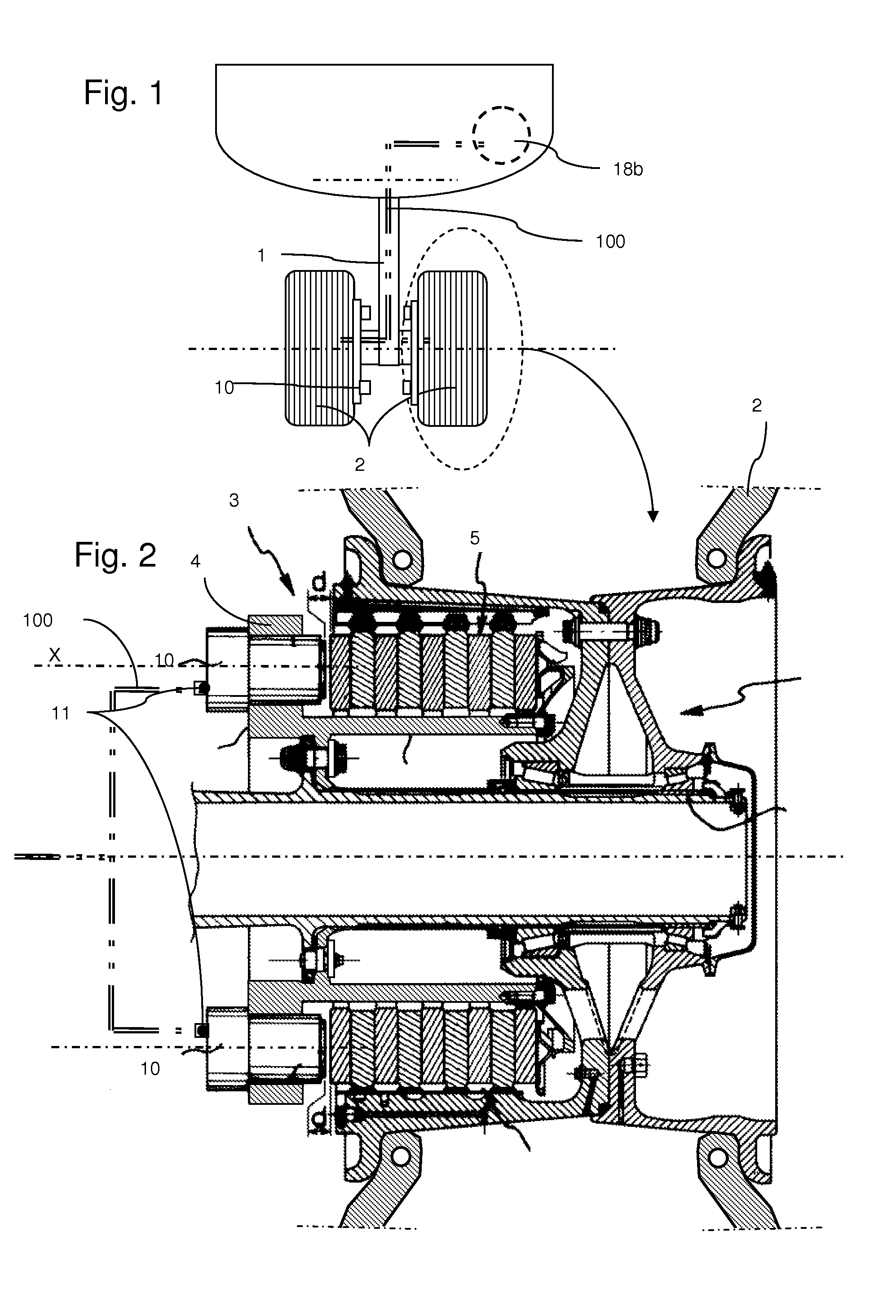
[0040]As shown in FIG. 1, the undercarriage 1 is hinged to the fuselage of the aircraft and includes a bottom end carrying wheels 2. Each of these wheels 2 is mounted to rotate on an axle of the undercarriage and is braked by means of a corresponding brake 3 that extends in part inside the wheel.

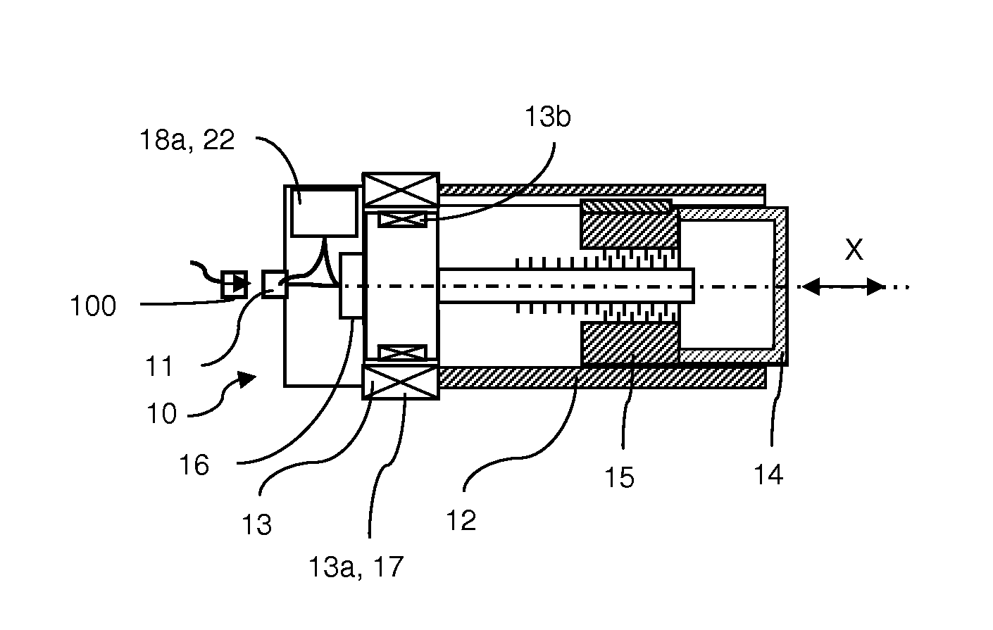
[0041]As shown in FIG. 2, the brake 3 has a plurality of brake actuators 10 (only two can be seen) carried by a ring 4. The actuators 10 extend facing a stack of disks 5 suitable for being selectively pressed together by the actuators 10 in order to brake the wheel associated with the brake. The actuators 10 are connected to the remainder of the braking architecture by electric cables 100 coming from the fuselage and going down along the undercarriage, these cables terminat...


PUM


Abstract

A braking actuator for a brake of an aircraft, the actuator comprising:an electric motor;a pusher actuated by the motor; anda position sensor for sensing the position of the movable portion of the motor and provided with transmitter and receiver members.The motor has first and second exciters adapted to move the movable portion of the motor and adapted to be powered independently from each other. The transmitter member of the position sensor comprises first and second transmitters adapted to be powered independently, and the receiver member generates the signal representative of position on being excited by at least one of the transmitters.

Description

[0001]The present invention relates to the field of brakes for aircraft wheels, and in particular to the field of electromechanical actuators adapted to actuate such brakes.[0002]Electromechanical brake actuators are known that comprise a plurality of actuators, each having a casing that integrates:[0003]an electric motor provided with a stationary portion and a movable portion;[0004]a pusher movable in translation relative to the casing along a pusher travel axis;[0005]mechanical means for transforming a travel movement of the movable portion into a movement in translation of the pusher; and[0006]a position sensor for sensing the position of the movable portion relative to the stationary portion.[0007]The stationary portion of the motor carries an exciter member adapted to cause the movable portion to move relative to said stationary portion when said exciter member is electrically powered. The sensor is generally of the inductive type and comprises a transmitter member and a recei...

Claims


Application Information

Patent Timeline
Patent Type & Authority Patents(United States)
IPC IPC(8): F16D65/28F16D55/36H02K7/06H02K11/00
CPCH02K7/06H02K11/0015H02K11/0073H02K11/21H02K11/33H02K2213/09
Inventor THIBAULT, JULIENNIERLICH, FLORENT
Owner SAFRAN LANDING SYSTEMS
Why Eureka
Try Eureka