
Contact prevention film, touch panel and display device cover panel

a technology of contact prevention film and touch panel, which is applied in the field of contact prevention film, touch panel and display device cover panel, can solve the problems of black stains, small optical protrusions of antireflection film, and easy crushing of antireflection film against the opposing surface, so as to reduce the haze value, prevent black stains, and improve the optical properties of coherence prevention film.

Inactive Publication Date: 2017-01-31
SOKEN CHEM & ENG CO LTD
View PDF13 Cites 2 Cited by
  • Summary
  • Abstract
  • Description
  • Claims
  • Application Information

AI Technical Summary

Benefits of technology

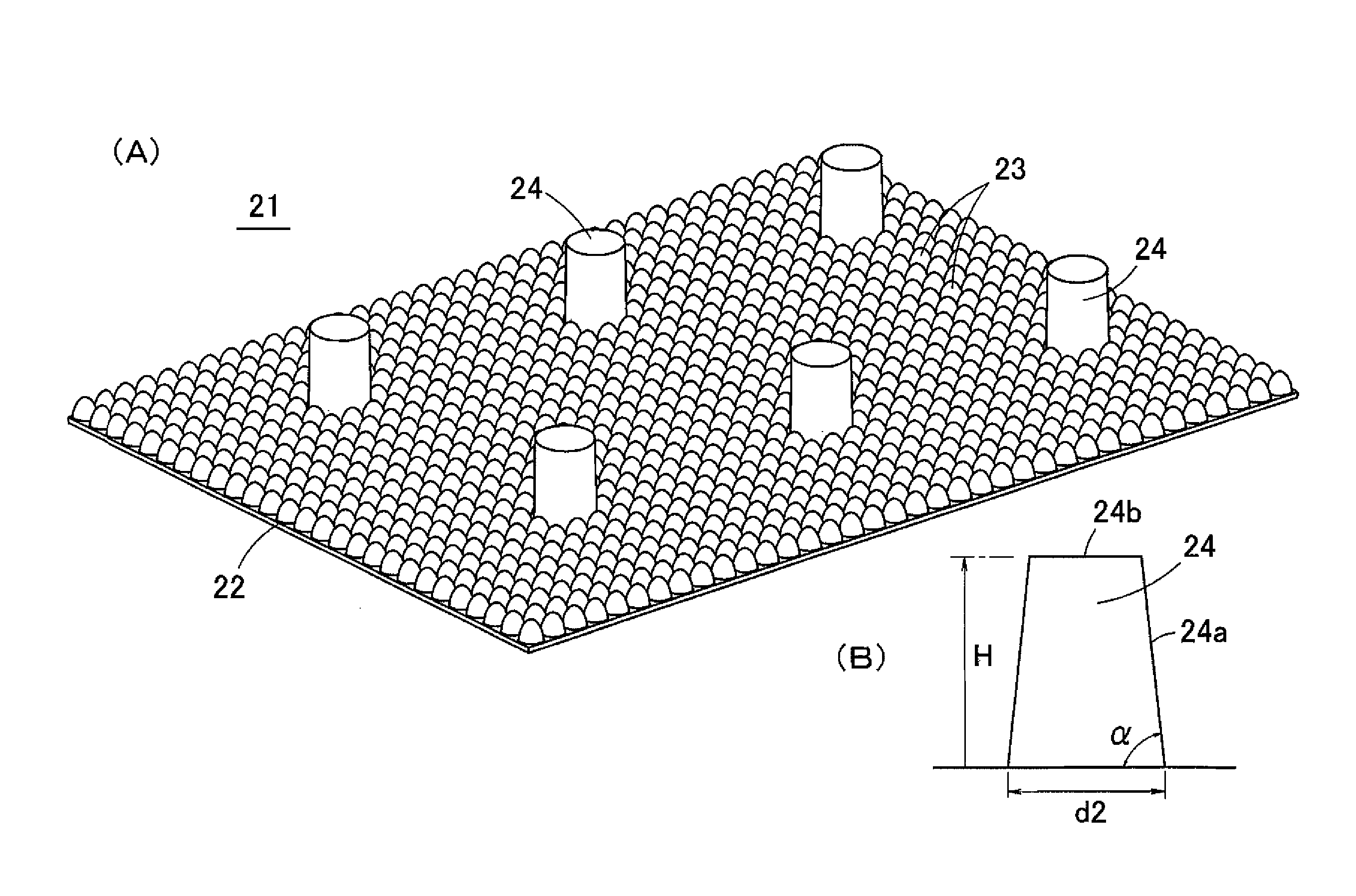
[0022]Since the coherence prevention film of the present invention is arranged in that the lateral surface projection occupying area rate of the projection is not more than 0.25%, light will be reflected by the projections and hardly returns when light enters the coherence prevention film through rear surface incidence so that the difference in reflectance between cases in which the light enters through rear surface incidence onto the coherence prevention film and in which it enters through front surface incidence becomes small. It is also possible to make the haze value of the projection small. Moreover, even when the projection is pressed by an opposing member (such as an image display panel), it is possible to prevent generation of a black stain caused by a black looking projection. Still further, since the projections are arranged in that their sectional areas of sections that are parallel to the surface of the film substrate become gradually smaller in approaching from an base end portion side towards a tip end portion side (for instance, frustum shaped projections), the projections easily come off from the forming dies at the time of forming the coherence prevention film. Particularly when the lateral surface projection occupying area rate of the projections is defined to be not more than 0.01%, the projections come easily off from the forming dies.
[0024]In an embodiment of the coherence prevention film according to the present invention, it is desirable to set an inclination angle of at least abase end portion of the lateral surfaces of the projection to be not less than 80 degrees and below 90 degrees. By defining the inclination angle of at least the base portion of the lateral surfaces of the projection to be in this range, it is possible to more reliably improve optical properties of the coherence prevention film. More particularly, it is possible to make the difference in reflectance small in cases of rear surface incidence and front surface incidence, to make the haze value small and to prevent black stains from forming at spots of projections when they are pressed.
[0025]In another embodiment of the coherence prevention film according to the present invention, it is desirable that the inclination angle of at least the base end portion of the lateral surfaces is not more than 88 degrees. According to such an embodiment, the projections come more easily and reliably off from forming dies.
[0027]In still another embodiment of the coherence prevention film according to the present invention, an antireflection structure comprised of a plurality of minute optical protrusions is formed on the surface of the film substrate. Such an embodiment applies when the coherence prevention film is configured as an antireflection film. In such a coherence prevention film, it is possible to achieve protection through the projections so that the optical protrusions will not be crushed.
[0029]Also in case the coherence prevention film of the present invention is affixed to a touch panel (particularly to a rear surface of a touch panel), optical properties such as reflectance and haze value are hardly reduced. Further, black stains are hardly generated at spots of the projections when the touch panel is pressed with a finger or a touch pen. Accordingly, it is possible to improve qualities of the touch panel when the touch panel is affixed with the coherence prevention film of the present invention.
[0030]Similarly, when the coherence prevention film of the present invention is affixed to a display device cover panel (particularly a rear surface of the display device cover panel), it is possible to improve qualities of the display device cover panel.

Problems solved by technology

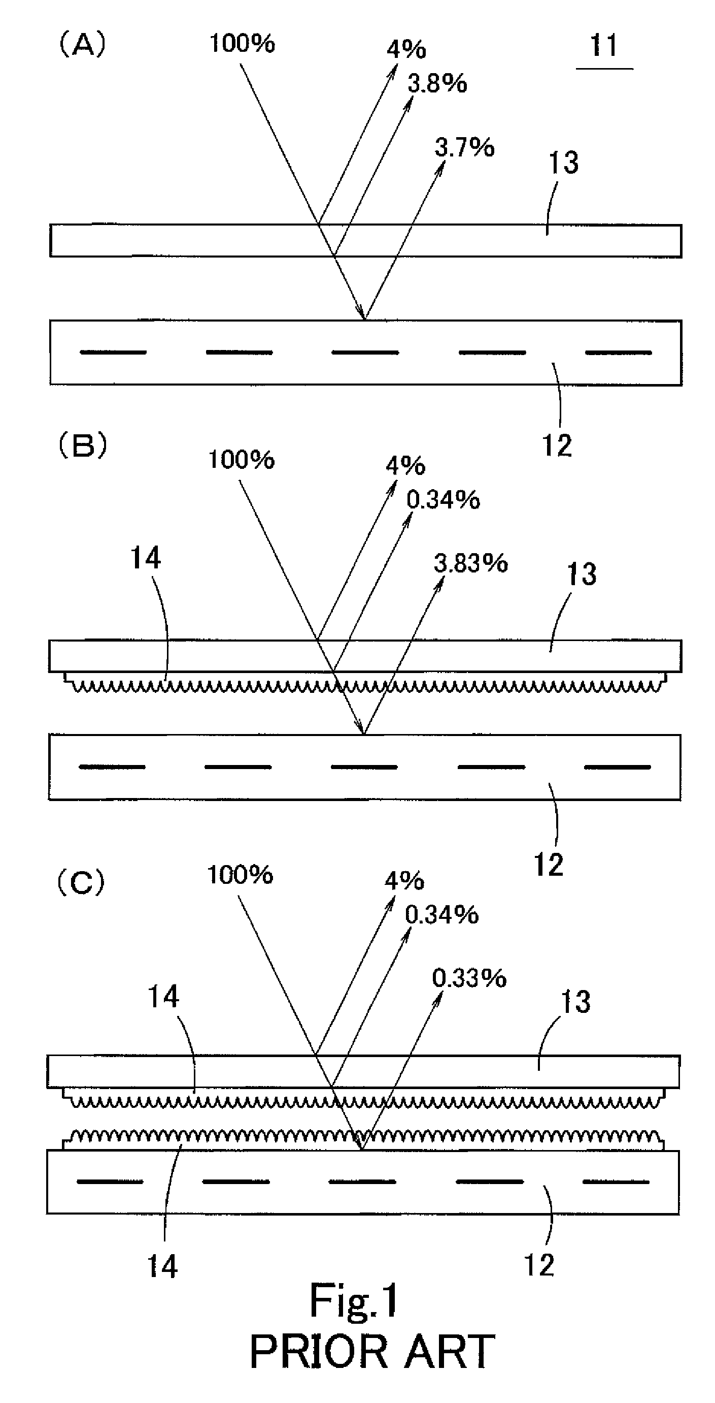
However, inconveniences are caused in display devices in that upon incidence of outside light such as sunlight or indoor illumination light on the screen, reflection of a part of the light on screens causes degradations of contrasts of images such that the screens become whitish.
Since the cover panel is pressed with a finger at the time of wiping the stains and sebum off the surface, when an antireflection film is affixed as in FIG. 1(B) or FIG. 1(C), the minute optical protrusions of the antireflection film are pressed against opposing surface and become easily crushed.
Further, in a display device comprising a touch panel on the surface thereof, the touch panel is pressed by a finger or a touch pen so that when antireflection film is affixed, it is also the case that the optical protrusions of the antireflection film are pressed against the opposing surface and become easily crushed.
Such crushing of the optical protrusions might result in degradations or damages of antireflection functions of the antireflection film.
However, in case of protection columns of pyramid shape, tip ends are apt to be crushed when the protection columns are pressed against an opposing surface.
Further, in case of protection columns of column shape having a uniform section, the mold releasability at the time of forming the antireflection film will be bad so that the protection columns will hardly part from forming dies, and it will be difficult to obtain protection columns of large height.
Accordingly, optical properties such as reflectance and haze value differ largely between cases in which the antireflection film is affixed to the front surface of the liquid crystal panel (in cases of front surface incidence) and in which it is affixed to the rear surface of the cover panel (in cases of rear surface incidence) which was inconvenient in view of design or use of the display devices which made it hard to use those films.

Method used


Image

  • Contact prevention film, touch panel and display device cover panel
  • Contact prevention film, touch panel and display device cover panel
  • Contact prevention film, touch panel and display device cover panel

Examples


first embodiment

[0101](First Embodiment of the Display Device)

[0102]FIG. 14(A) and FIG. 14(B) show a first embodiment of the display device affixed with the antireflection film 21 according to the present invention. The display device 31 as shown in FIG. 14(A) is obtained by overlapping a cover panel 33 to a front surface of an image display panel 32 such as a liquid crystal display panel (LCD) or organic EL (OLED) with an air gap (space) interposed between, and the antireflection film 21 is affixed onto a rear surface of the cover panel 33. The display device 31 as shown in FIG. 14(B) is affixed with the antireflection film 21 on the front surface of the image display panel 32. In this respect, the image display panel 32 might be either for monochrome display or for color display. The cover panel 33 is a protection sheet of uniform thickness made of transparent resin.

[0103]In the antireflection film 21 of the present invention, the difference in optical properties such as reflectance and haze valu...

second embodiment

[0107](Second Embodiment of the Display Device)

[0108]FIG. 17(A) shows a second embodiment of the display device affixed with the antireflection film 21 according to the present invention. This display device 41 is obtained by overlapping a touch panel 42 to a front surface of an image display panel 32 such as a liquid crystal display panel (LCD) or organic EL (OLED) with an air gap (space) interposed between, and the antireflection film 21 is affixed onto a rear surface of the touch panel 42.

[0109]As shown in FIG. 17(A), the touch panel 42 comprises a touch panel substrate 43 that propagates surface acoustic waves and a sheet material 44 that is disposed to oppose the touch panel substrate 43 and that can contact the touch panel substrate 43 by pressing. A peripheral edge portion of the touch panel substrate 43 and a rear surface peripheral edge portion of the sheet material 44 are joined by a spacer 50 of frame-like shape, and a closed space surrounded by the spacer is formed betwe...


PUM

PropertyMeasurementUnit
inclination angleaaaaaaaaaa

Abstract

Means of solution: Optical protrusions 23 of nano-size for restricting reflection of light and protection columns 24 for preventing crushing of the optical protrusions 23 are provided on a surface of a film substrate 22. The protection columns 24 have a frustum shape. When a ratio of a projection area in which all of lateral surfaces of a single protection column 24 are projected on a surface of the film substrate 22 from a direction that is perpendicular to the surface of the film substrate 22 to a divided area on the surface of the film substrate 22 with respect to the single protection column 24 is defined to be a lateral surface projection occupying area rate, the lateral surface projection occupying area rate of the antireflection film is not more than 0.25% and not less than 0.01%.

Description

TECHNICAL FIELD[0001]The present invention relates to a contact prevention film, a touch panel and a display device cover panel. More particularly, the present invention relates to a contact prevention film that hardly coheres to an opposing member when pressed with a finger or the like. It also relates to a touch panel and a display device cover panel comprising the present coherence prevention film as an application thereof.BACKGROUND ARTActions of an Antireflection Film[0002]Various kinds of equipment such as mobiles phones, mobile computers and personal computers comprise display devices that are capable of displaying definite images. However, inconveniences are caused in display devices in that upon incidence of outside light such as sunlight or indoor illumination light on the screen, reflection of a part of the light on screens causes degradations of contrasts of images such that the screens become whitish.[0003]Such a phenomenon of reflection of outside light is caused as sh...

Claims


Application Information

Patent Timeline
Patent Type & Authority Patents(United States)
IPC IPC(8): G02B13/20G02B1/10G02B5/02G06F1/16G02B1/118G02F1/1335G02F1/1333G02B27/00G06F3/043
CPCG02B1/10G02B1/118G02F1/13338G02F1/133502G06F1/169G02F2001/133331G02F2201/50G06F3/0436G02B1/18G02F1/133331
Inventor KATO, TOMONOBUMINOBE, TETSUYATAKAGI, YOSHIHIKOYAMAMOTO, YUKI
Owner SOKEN CHEM & ENG CO LTD
Learn More