Method for determining an emergency braking situation of a vehicle

a technology for emergency braking and vehicles, applied in the direction of process control, pedestrian/occupant safety arrangement, instruments, etc., can solve the problems of triggering emergency braking, unnecessarily, etc., and achieve the effect of reliable recognition of emergency braking situation and keeping the likelihood of unwarranted emergency braking low

Active Publication Date: 2017-02-14
ZF CV SYST EURO BV
View PDF49 Cites 115 Cited by
  • Summary
  • Abstract
  • Description
  • Claims
  • Application Information

AI Technical Summary

Benefits of technology

[0008]Generally speaking, it is an object of the present invention to provide a method, a corresponding control device to carry it out, and a driving dynamics control system, that enable reliable recognition of an emergency braking situation and keep the likelihood of unwarranted emergency braking low.
[0024]Thus, a reliable method that can be implemented at relatively low computing costs is provided, which reliably detects different initial movement states of the subject vehicle and of the object ahead. Unnecessarily early emergency braking with risks arising therefrom both to the subject vehicle and possibly also to following vehicles are thereby excluded with high reliability.
[0028]The control device according to an embodiment of the present invention can cap the torque of the engine, especially depending on the result of the method used to assess whether an emergency braking situation is presented, for which it e.g., outputs control signals to an engine controller.

Problems solved by technology

Such conventional methods have the disadvantage that, in general, they are often restricted to only special driving situations and thus do not always contribute in a timely manner to avoiding accidents by autonomous braking.
Furthermore, triggering of emergency braking may also take place too early and thus possibly unnecessarily.

Method used


Image

  • Method for determining an emergency braking situation of a vehicle
  • Method for determining an emergency braking situation of a vehicle
  • Method for determining an emergency braking situation of a vehicle

Examples


Embodiment Construction

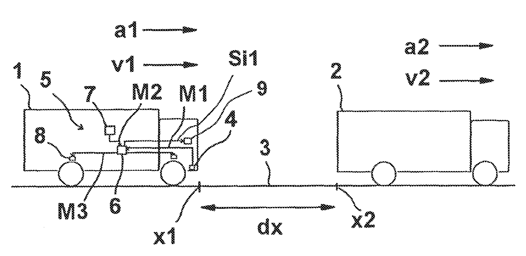
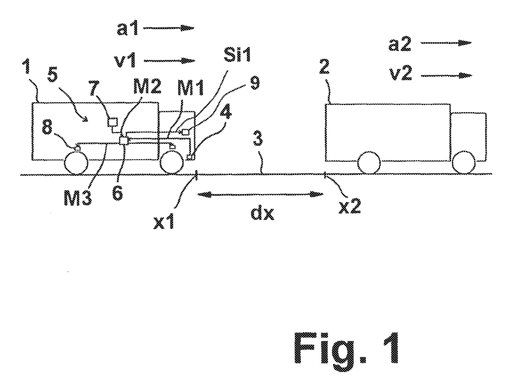
[0084]Referring now to the drawing figures, FIG. 1 depicts a first subject vehicle 1 driving on a road 3 behind an object ahead 2, in this case a second vehicle 2 ahead. Only movements in the common vehicle longitudinal direction are considered below. The first subject vehicle 1 is located at a position x1 and is traveling at a speed v1 and with an acceleration a1. A braking process thus constitutes an acceleration a1 with a negative value. Accordingly, the second vehicle ahead 2 is at a position x2, traveling at a second speed v2 and with a second acceleration a2. All variables x1, v1, a1; x2, v2, a2 are time dependent. Consequently, second order equations of motion in the time domain are established for the two vehicles, the first subject vehicle 1 and the vehicle ahead 2. Preferably, a constant first subject acceleration and second acceleration a1, a2 are assumed here, at least until the initiation of a braking process of the subject vehicle 1.

[0085]The subject vehicle 1 comprise...


PUM


Abstract

To determine whether an emergency braking situation exists for a vehicle, the vehicle determines at least the following state variables: its own velocity, its own longitudinal acceleration, its relative distance from an object in front, and the speed and acceleration of the object in front. A suitable evaluation method to assess whether an emergency braking situation is present is determined as a function of these state variables from a plurality of evaluation method options, including at least a movement equation evaluation method in which a movement equation system of the vehicle and of the object in front is determined, and an evaluation method in which a braking distance of the vehicle is determined.

Description

FIELD OF THE INVENTION[0001]The present invention generally relates to a method for determining an emergency braking situation of a vehicle (e.g., risk of a rear impact), a control device for carrying out the method and a driving dynamics control system equipped with the control device.BACKGROUND OF THE INVENTION[0002]It is generally known to establish equations of motion in order to determine a collision time for the current driving behavior of a vehicle and of a vehicle ahead. It is also generally known to determine target decelerations in order to avoid possible collisions.[0003]EP 1 539 523 B1 and DE10258617B4 disclose a method and a device for triggering an automatic emergency braking process of a vehicle. The speed and the acceleration of the subject vehicle are determined and a minimum distance is set as a target safety distance. Furthermore, a target relative speed between the two vehicles is set that should be reached at the end of the automatic emergency braking process. I...

Claims


Application Information

Patent Timeline
Patent Type & Authority Patents(United States)
IPC IPC(8): B60T7/12B60T7/22G08G1/16B60R21/0134B60K31/00B60W10/18B60W30/09
CPCB60T7/22B60R21/0134G08G1/161G08G1/166B60K2031/0033B60W10/18B60W30/09B60W2520/10B60W2520/105B60W2550/302B60W2550/308B60W2554/804B60W2554/801B60R21/013B60T7/12B60W40/10G08G1/16B60W30/08
Inventor BREUER, KARSTENSANDKUHLER, DIRK
Owner ZF CV SYST EURO BV
Why Eureka
Try Eureka