
Filter device and arrangement for ventilating a tank comprising a filter device

a filter device and filter device technology, which is applied in the direction of transportation and packaging, separation processes, containers, etc., can solve the problems of reducing the maximum torque, affecting the startability of the engine, and difficult filtering of small particles on the fuel filter

Active Publication Date: 2017-02-21
VOLVO LASTVAGNAR AB
View PDF20 Cites 1 Cited by
  • Summary
  • Abstract
  • Description
  • Claims
  • Application Information

AI Technical Summary

Benefits of technology

This patent describes the use of air breather filters in vehicles to improve engine performance and fuel efficiency. These filters help to catch small particles that can damage engine components, which can lower the engine's lifespan. When the filter gets wet, it increases the pressure drop, which negatively impacts engine startability and fuel consumption. The invention aims to address this issue by arranging the filter at a specific tank system, which prevents a significant pressure drop on the main tank and allows for better fuel consumption in the slave tank.

Problems solved by technology

These small particles are difficult to filtrate on fuel filters.
This pressure drop has a negative impact on engine startability, lowers the maximum torque and increases the fuel consumption on all trucks somewhat.
This leakage is causing filter papers of air filters connected to the fuel tank to get soaked with fuel, leading to an increased pressure drop.
This pressure drop causes an unbalance of fuel levels on dual tanks which are commonly used in commercial vehicles, as each tank has its own air filter, and clogging occurs mainly on master side.
The result is that a significant amount of fuel cannot be consumed also the fuel is carried in the tank.
Favourably, the normal operation of the air filter is undisturbed in case a leakage of fuel from inside of the fuel tank occurs.
Such a situation can happen when the filter device is mounted in a vehicle where the filter device experiences rough conditions during use of the vehicle.
For instance, rain water can enter the filter device under unfavourable conditions.
As a result the amount of fuel available in the slave tank can be consumed in the master tank.

Method used


Image

  • Filter device and arrangement for ventilating a tank comprising a filter device
  • Filter device and arrangement for ventilating a tank comprising a filter device
  • Filter device and arrangement for ventilating a tank comprising a filter device

Examples


second embodiment

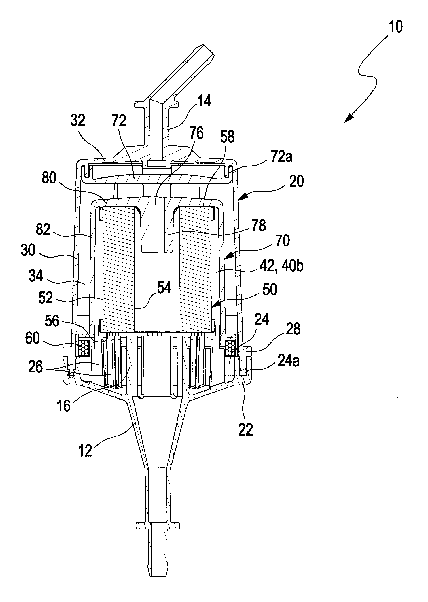
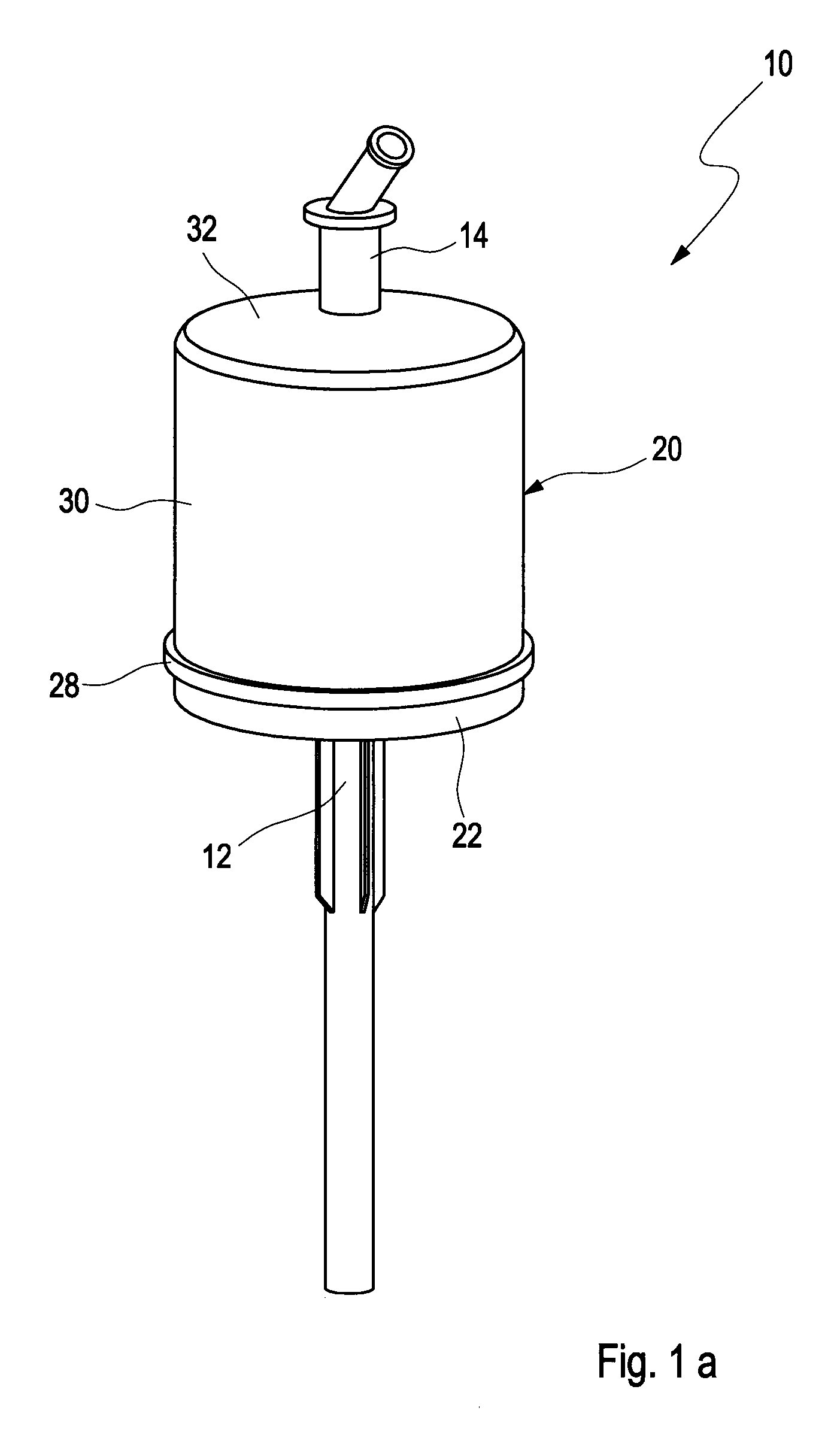
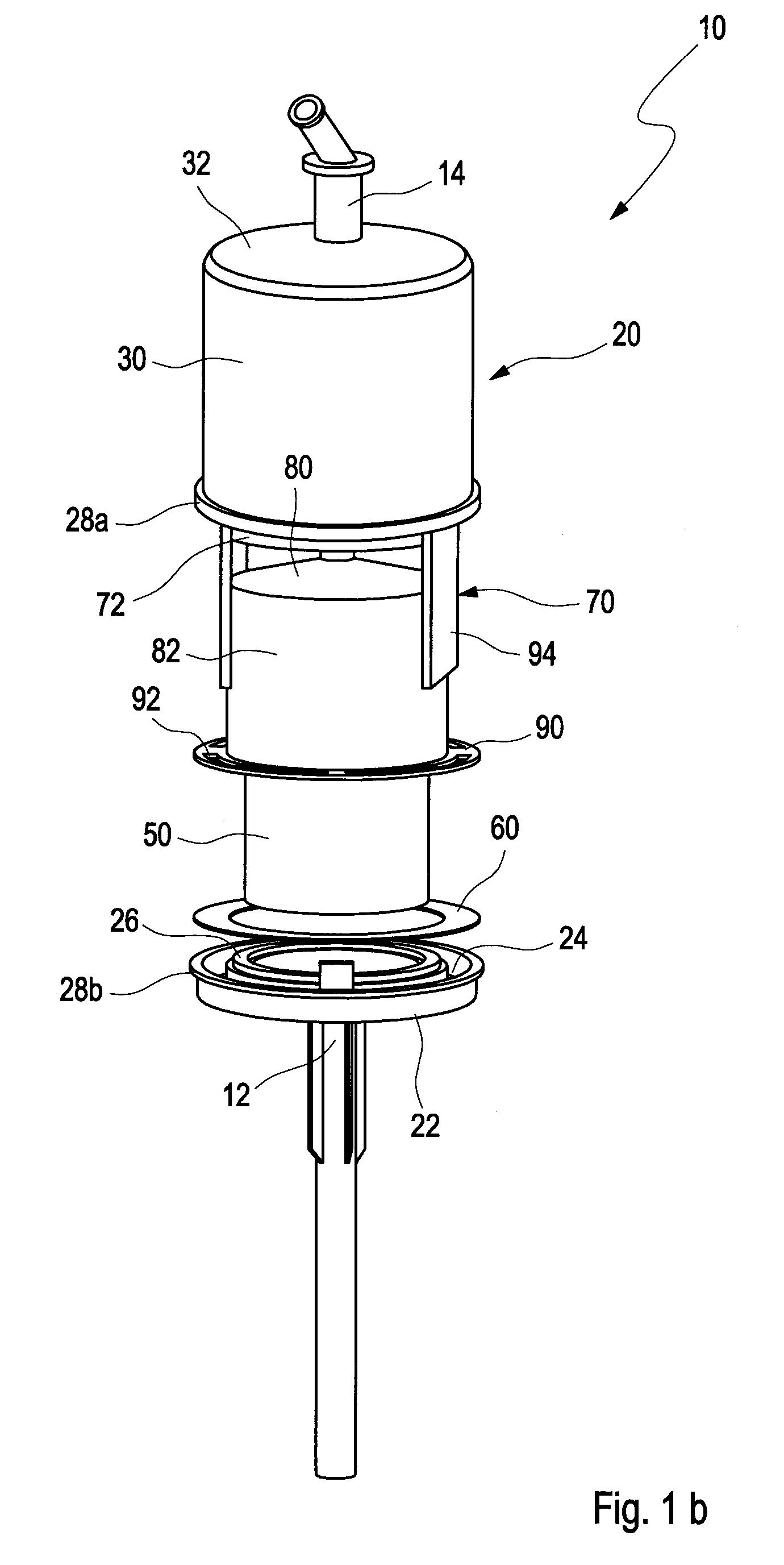
[0046]FIGS. 2a to 2d depict a filter device 10 according to the invention. A perspective view of the filter device 10 is shown in FIG. 2a, and in an exploded view in FIG. 2b. FIGS. 2c and 2d show longitudinal cut views with some elements removed for clarity in FIG. 2d.

[0047]It should be mentioned that, although the filter device 10 is shown in all embodiments with a filter 50 having a vertical axis, the filter device 10 can also be a horizontal arrangement by tilting the filter device 10 by 90° so that the filter axis is arranged horizontally. However, it is expedient to leave the first port 12 in the lowest position of the filter device 10.

first embodiment

[0048]As in the first embodiment, the filter device 10 comprises a housing 20 with a first port 12 being provided as an inlet (for instance an air inlet) in normal operation of the filter device 10 and a second port 14 being provided as an outlet (for instance an air outlet) under normal operation of the filter device 10. Tubes or hoses may be attached to the ports 12, 14 (not shown). The second port 14 is attached to a tank, for instance a fuel tank (not shown) which is to be ventilated through the filter device 10.

[0049]The housing 20 may have a generally cylindrical or slightly conical shape with a cylindrical shell 30 arranged around the longitudinal extension of the filter device 10, and a bottom part 22 and a top part 32. As can be seen, the first port 12 is provided with a conical transition from a cylindrical tube to the bottom part 22. Expediently, the bottom part 22 is cup-shaped with a low wall portion in longitudinal direction.

[0050]The first port 12 is arranged in the c...


PUM

PropertyMeasurementUnit
pressure dropaaaaaaaaaa
distanceaaaaaaaaaa

Abstract

A filter device, particularly an air breather filter device for venting a fuel tank, includes a housing with a first port provided as an inlet in normal operation of the filter device and a second port provided as an outlet under normal operation of the filter device. The housing encloses at least one filter and an air passage extends from the first port to the second port passing through the filter. Inside the housing a baffle unit is arranged in the housing for covering the at least one first filter in relation to the second port, wherein the baffle unit is arranged to deflect a fluid flow entering the filter device through the second port.

Description

BACKGROUND AND SUMMARY[0001]The invention relates to a filter device, particularly an air breather filter device for a tank, and an arrangement for ventilating a tank comprising a filter device.[0002]Air breather filters are commonly utilized in vehicles, particularly commercial vehicles such as trucks and buses. They consist of filter paper to be able to catch especially small particles of down to 4 μm and smaller. These small particles are difficult to filtrate on fuel filters. Trapping these small particles increases the lifetime of engine components such as fuel pump and injectors strongly. When the filter paper gets wet, the pressure drop through the filter paper is increased dramatically. An amount of only 5 g diesel is enough to fully soak existing filter papers and changes the pressure drop over the filter from 0 mbar to around 20 to 30 mbar. This pressure drop has a negative impact on engine startability, lowers the maximum torque and increases the fuel consumption on all t...

Claims


Application Information

Patent Timeline
Patent Type & Authority Patents(United States)
IPC IPC(8): B60K15/035B01D46/00B01D50/00B01D45/08B60K15/03B01D46/08
CPCB60K15/035B01D46/0043B01D46/08B01D50/002B60K2015/03236B01D46/2403B01D2279/35B60K2015/03125B01D50/20B01D45/08
Inventor SONDEREGGER, SIGURDLEXEN, JONAS
Owner VOLVO LASTVAGNAR AB
Learn More