
Light-emitting module

a technology of light-emitting modules and light-emitting components, which is applied in the direction of semiconductor devices for light sources, lighting and heating apparatus, planar light sources, etc., can solve the problems of non-uniform mixing of light, environmental or application, and the inability of conventional techniques to adjust the white light rendering effect according to the product attribute, etc., and achieves a better white light color rendering index

Active Publication Date: 2017-02-28
EDISON-OPTO
View PDF2 Cites 29 Cited by
  • Summary
  • Abstract
  • Description
  • Claims
  • Application Information

AI Technical Summary

Benefits of technology

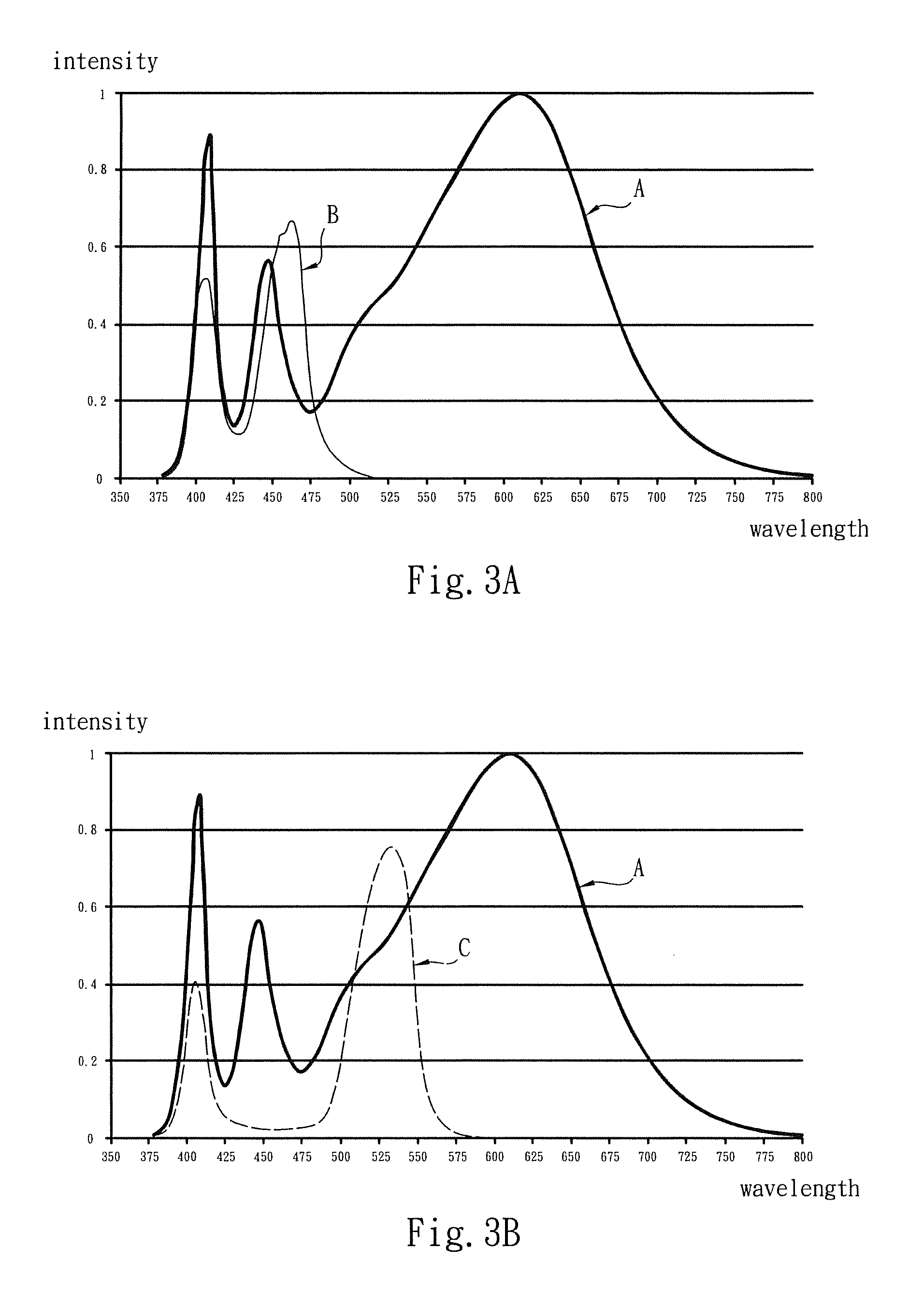
The present invention provides a light-emitting module that has better white light color rendering index. The module includes an ultraviolet ray emitter and a blue light emitter. A wavelength conversion layer is laid on the substrate board, which includes a first wavelength conversion material and a second wavelength conversion material. The first material converts the light emitted from the ultraviolet ray emitter into visible light and the second material converts the light emitted from the blue light emitter into white light. This achieves a white general output optical spectrum that meets the requirements of many application situations. The ultraviolet ray emitter is an ultraviolet ray emitting diode and the blue light emitter is a blue light emitting diode. The first material includes at least one UV fluorescent material and the second material includes at least one fluorescent material.

Problems solved by technology

With respect to the structure and application of the conventional white light emitting module, the conventional technique cannot adjust the white light rendering effect according to the product attribute, environment or application condition.
The conventional technique cannot solve the problem of non-uniform mixing of the light.

Method used


Image

  • Light-emitting module
  • Light-emitting module
  • Light-emitting module

Examples


Embodiment Construction

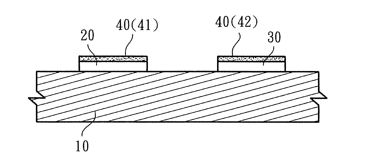
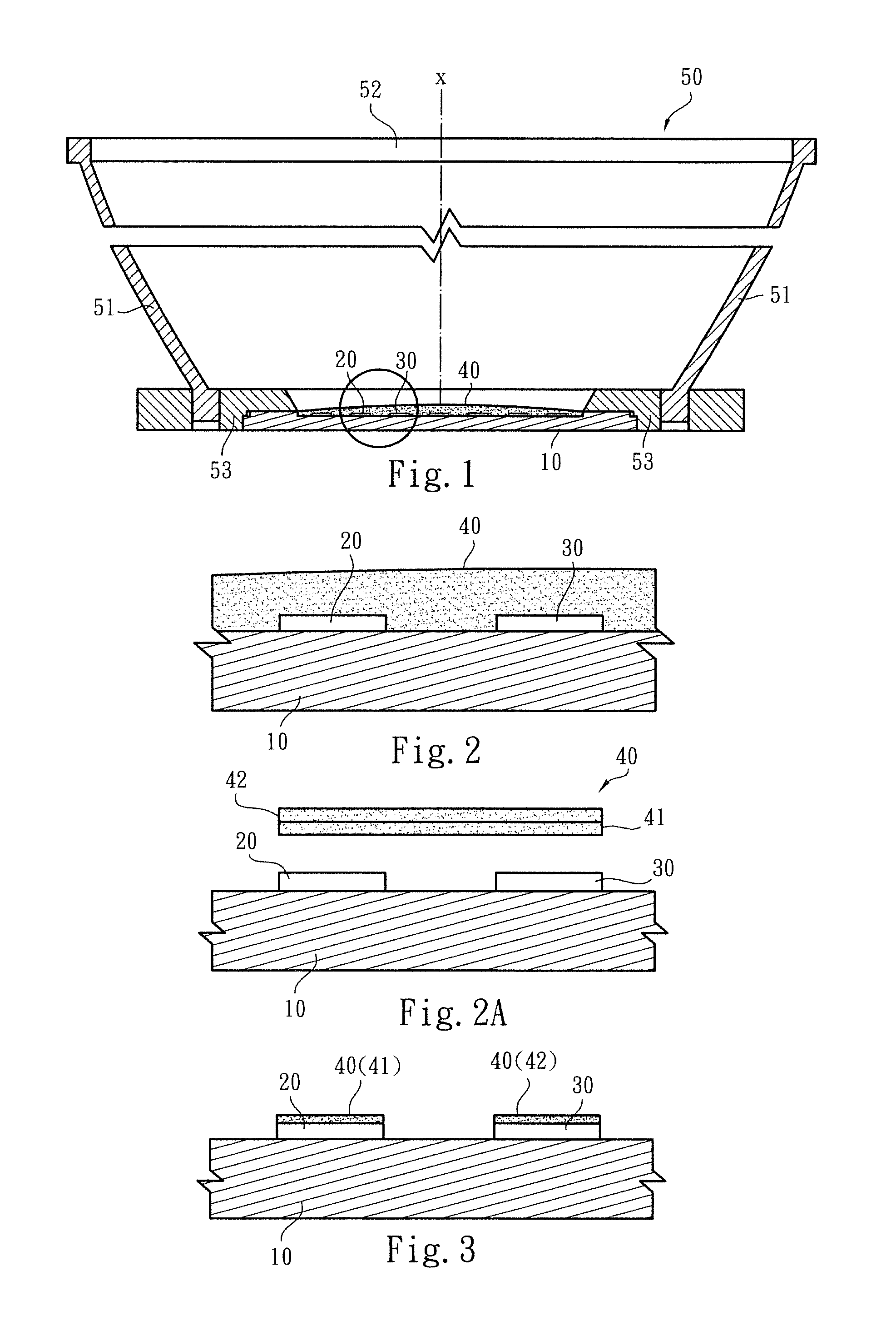
[0024]Please refer to FIGS. 1, 2 and 3. The light-emitting module of the present invention includes a substrate board 10 in a geometrical form. The substrate board 10 is selected from a group consisting of an electro-conductive and heat conduction metal substrate board (such as copper substrate board or aluminum substrate board), circuit board and ceramic substrate board. At least one ultraviolet ray emitter 20 and at least one blue light emitter 30 are disposed on the substrate board 10. The ultraviolet ray emitter 20 is selectively an ultraviolet ray emitting diode with a light wavelength or optical spectrum ranging from 380 nm to 420 nm. The blue light emitter 30 is selectively a blue light emitting diode with a light wavelength or optical spectrum ranging from 440 nm to 470 nm. A wavelength conversion layer 40 is laid on the substrate board 10 to at least receive the light emitted from the ultraviolet ray emitter 20 and the blue light emitter 30. The wavelength conversion layer ...


PUM


Abstract

A light-emitting module has better white light color rendering index to provide white rendering effect in accordance with the requirements of various application sites. The light-emitting module includes a (circuit) substrate board and at least one ultraviolet ray emitter and at least one blue light emitter disposed on the substrate board. The light wavelength of the ultraviolet ray emitter ranges from 380 nm to 420 nm. The light wavelength of the blue light emitter ranges from 440 nm to 470 nm. A wavelength conversion layer is laid on the substrate board. The wavelength conversion layer includes a first wavelength conversion material and a second wavelength conversion material for receiving and converting the light emitted from the ultraviolet ray emitter into visible light and the light emitted from the blue light emitter into white light. After the lights are mixed, a white general output optical spectrum is achieved.

Description

FIELD OF THE INVENTION[0001]The present invention relates generally to a light-emitting module including a combination of ultraviolet ray emitters, blue light emitters and a wavelength conversion layer. The wavelength conversion layer includes a first wavelength conversion material and a second wavelength conversion material for receiving and converting the light emitted from the ultraviolet ray emitter into visible light and the light emitted from the blue light emitter into white light. After the lights are mixed, a pure snow white light is output.BACKGROUND OF THE INVENTION[0002]A conventional light-emitting diode (LED) is used as a light source or illumination device. The LED is widely applied to various sites or environments. In conventional technique, a light-emitting module is often used to project white light onto an exhibited environment or product. The light-emitting module includes blue light LED. The light emitted from the blue light LED energizes yellow fluorescent powd...

Claims


Application Information

Patent Timeline
Patent Type & Authority Patents(United States)
IPC IPC(8): F21V9/16H01L25/075H01L33/50F21K99/00F21Y101/00
CPCF21V9/16H01L25/0753F21K9/00F21Y2101/00F21Y2105/10F21Y2115/10H01L33/504H01L2224/48137H01L2924/0002H01L2924/181H01L2924/00012H01L2924/00F21K9/68F21V9/08F21V13/08F21V9/32F21V9/38
Inventor WU, CHIEN-JUNGTSENG, KUO-FENGPAN, HAN-PIN
Owner EDISON-OPTO
Learn More