Cable connector assembly with an improved cable

a technology of cable connectors and connector assemblies, applied in the direction of power cables, power cable including electrical control, coupling device connections, etc., can solve the problems of damage to the outer insulative layers of adjacent single wires, and achieve good electrical connection

Inactive Publication Date: 2017-03-07
FOXCONN INTERCONNECT TECH LTD
View PDF14 Cites 21 Cited by
  • Summary
  • Abstract
  • Description
  • Claims
  • Application Information

AI Technical Summary

Benefits of technology

[0006]Accordingly, an object of the present invention is to provide a cable connector assembly with good electrically connection.

Problems solved by technology

When soldering the coaxial wires, outer insulative layers of adjacent single wires might be damaged.

Method used


Image

  • Cable connector assembly with an improved cable
  • Cable connector assembly with an improved cable
  • Cable connector assembly with an improved cable

Examples


Embodiment Construction

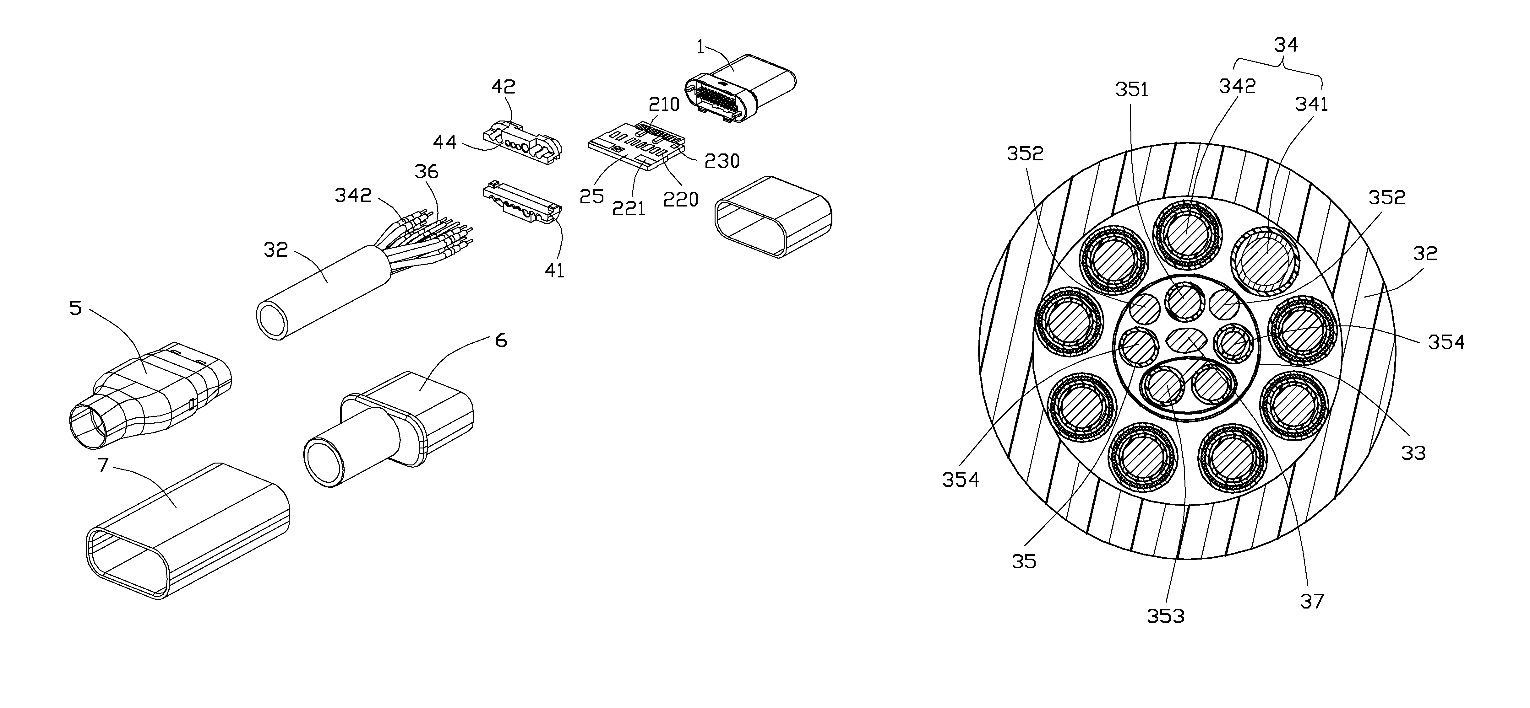
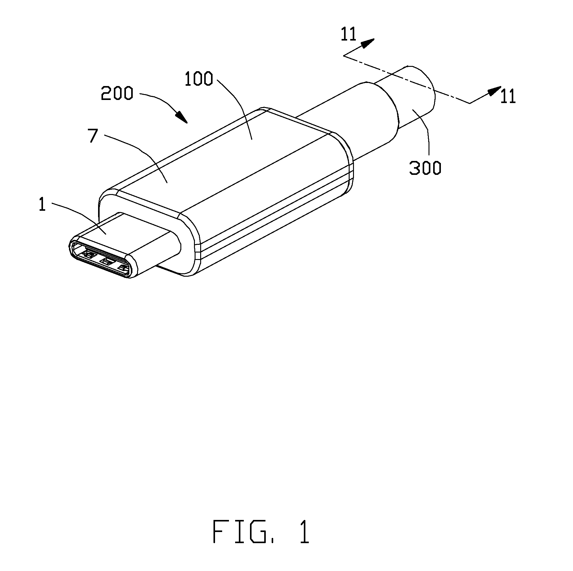
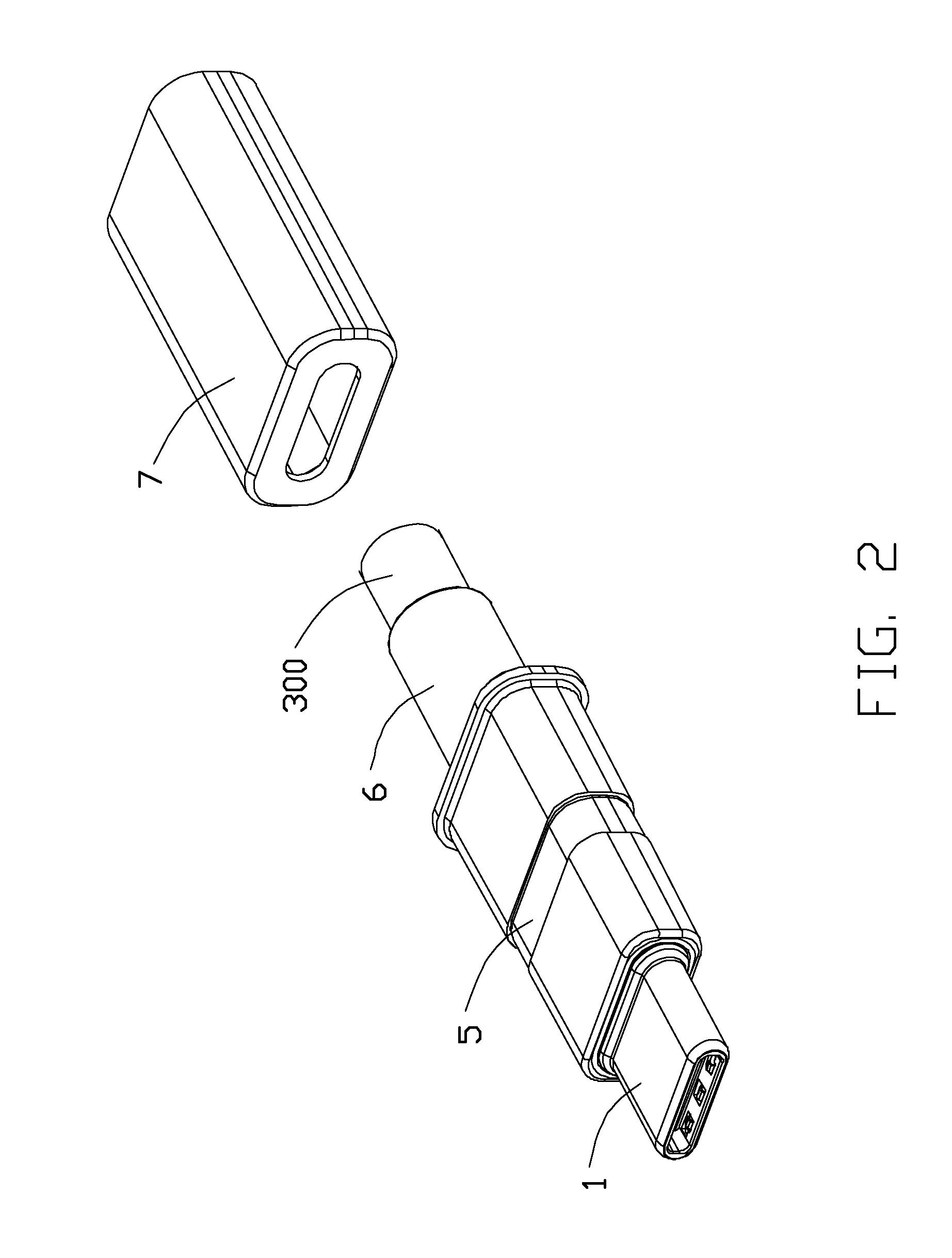
[0020]Referring to FIGS. 1-7, a cable connector assembly 200 in accordance with the present invention can be mated with a complementary connector. The cable connector assembly 200 comprises an electrical connector 100 and a cable 300 connecting with the electrical connector 100. The electrical connector 100 comprises a sub-connector 1, a printed circuit board (PCB) 2 electrically connected with the sub-connector 1, a cable 300 electrically connected with the printed circuit board 2, a retaining member 4 limiting the cable 300, an inner insulator 5 enclosing on the sub-connector 1 and the cable 300, a strain relief member 6 formed on the inner insulator 5 and the cable 300, and an outer cover 7. The cable connector assembly 200 is capable of mating with the complementary connector along a forward direction and a reverse direction to achieve the same function.

[0021]Referring to FIGS. 9-10, the sub-connector 1 comprises an insulative housing 11, a plurality of contacts 12 retained in t...


PUM

PropertyMeasurementUnit
diameteraaaaaaaaaa
conductiveaaaaaaaaaa
radiusaaaaaaaaaa

Abstract

A cable connector assembly includes an electrical connector (100) and cable (300) connected with the electrical connector. The cable has a plurality of core wires (31) including a plurality of first wires (34) and second wires (35), an outer jacket (32) enclosing on the core wires, and a shielding layer (33) enclosing the second wires. The first wires having a power wire (341) for power transmission and a plurality of coaxial wires (342) for high speed signal transmission, wherein the second wires have a detective wire (351) for detection signal transmission, a pair of ground-wires (352), a twisted pair wire (353) for USB 2.0 signal transmission an spare wire (354). Each of the first wires has a larger diameter than that of second wires, and the first wires are located between the shielding layer and outer jacket, the second wires are enclosed in the shielding layer.

Description

BACKGROUND OF THE INVENTION[0001]1. Field of the Invention[0002]The present invention relates to a cable connector assembly, and more particularly to a structure of core wires thereof.[0003]2. Description of Related Art[0004]U.S. Pat. No. 8,133,071, issued on Mar. 13, 2012, shows a cable connector assembly including a flat cable and a flexible printed circuit. The cable defines a row of core wires and an insulative layer enclosing the core wires. The core wires comprise a plurality of coaxial cables and a plurality of single wires. The flexible printed circuit comprises a plurality of pads arranged in a line and a lengthwise grounding portion separated from the pads. Each coaxial cable comprises an inner conductor connected to a corresponding pad and an outer conductor connected to the grounding portion. The single wires comprise a plurality of power wires connected to corresponding pads and a plurality of grounding wires connected to the grounding portion. The coaxial cables and th...

Claims


Application Information

Patent Timeline
Patent Type & Authority Patents(United States)
IPC IPC(8): H01B9/00H01R13/6585H01R13/66H01B11/00H01B11/06
CPCH01R13/6585H01B9/003H01B9/006H01B11/002H01B11/06H01R13/665
Inventor WU, JERRYCHEN, JUNMENG, FAN-BO
Owner FOXCONN INTERCONNECT TECH LTD
Why Eureka
Try Eureka