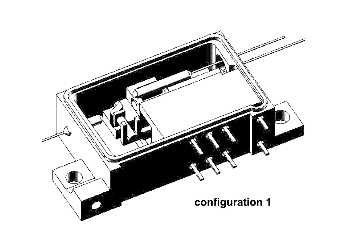
Fiber optical switches

a fiber optic switch and fiber optic technology, applied in the field of optical communication, can solve the problems of affecting the reliability of components, affecting the use of optical components, and affecting the performance of optical components, so as to avoid obscuring the purpose

Active Publication Date: 2017-03-14
ALLIAN FIBER OPTIC PROD INC
View PDF48 Cites 1 Cited by
  • Summary
  • Abstract
  • Description
  • Claims
  • Application Information

AI Technical Summary

Benefits of technology

[0008]This section is for the purpose of summarizing some aspects of the present invention and to briefly introduce some preferred embodiments. Simplifications or omissions may be made to avoid obscuring the purpose of the section. Such simplifications or omissions are not intended to limit the scope of the present invention.

Problems solved by technology

Although there are lead-free solders available now, higher melting temperature to use them can cause the fixation process more stressful, leading to reliability issues.
Also many optical components being soldered may not withstand the high temperature that can weaken the reliability of the components.
This prompts the industry to rethink if there are alternative approaches to make optical switches.

Method used


Image

  • Fiber optical switches
  • Fiber optical switches
  • Fiber optical switches

Examples


Embodiment Construction

[0024]In the following description, numerous specific details are set forth in order to provide a thorough understanding of the present invention. However, it will become obvious to those skilled in the art that the present invention may be practiced without these specific details. The description and representation herein are the common means used by those experienced or skilled in the art to most effectively convey the substance of their work to others skilled in the art. In other instances, well-known methods, procedures, components, and circuitry have not been described in detail to avoid unnecessarily obscuring aspects of the present invention.

[0025]Reference herein to “one embodiment” or “an embodiment” means that a particular feature, structure, or characteristic described in connection with the embodiment can be included in at least one embodiment of the invention. The appearances of the phrase “in one embodiment” in various places in the specification are not necessarily al...


PUM


Abstract

Various designs of optical switch are disclosed. In one embodiment, the optical switch uses wedges to hold up a collimator and secure the wedges and collimator to a substrate with a type of adhesive, thus avoiding high temperature in soldering process. There are at least two assemblies bonded to the substrate using the adhesive. Each of the assemblies includes a collimator and two wedges, where the wedges are provided to physically hold up the collimator in position. The assemblies are glued directly to the substrate after an optical alignment is performed.

Description

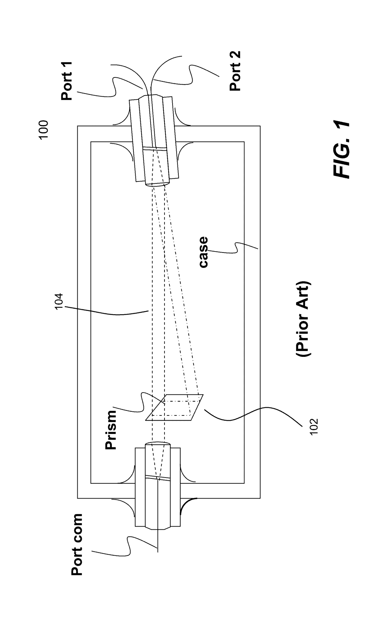
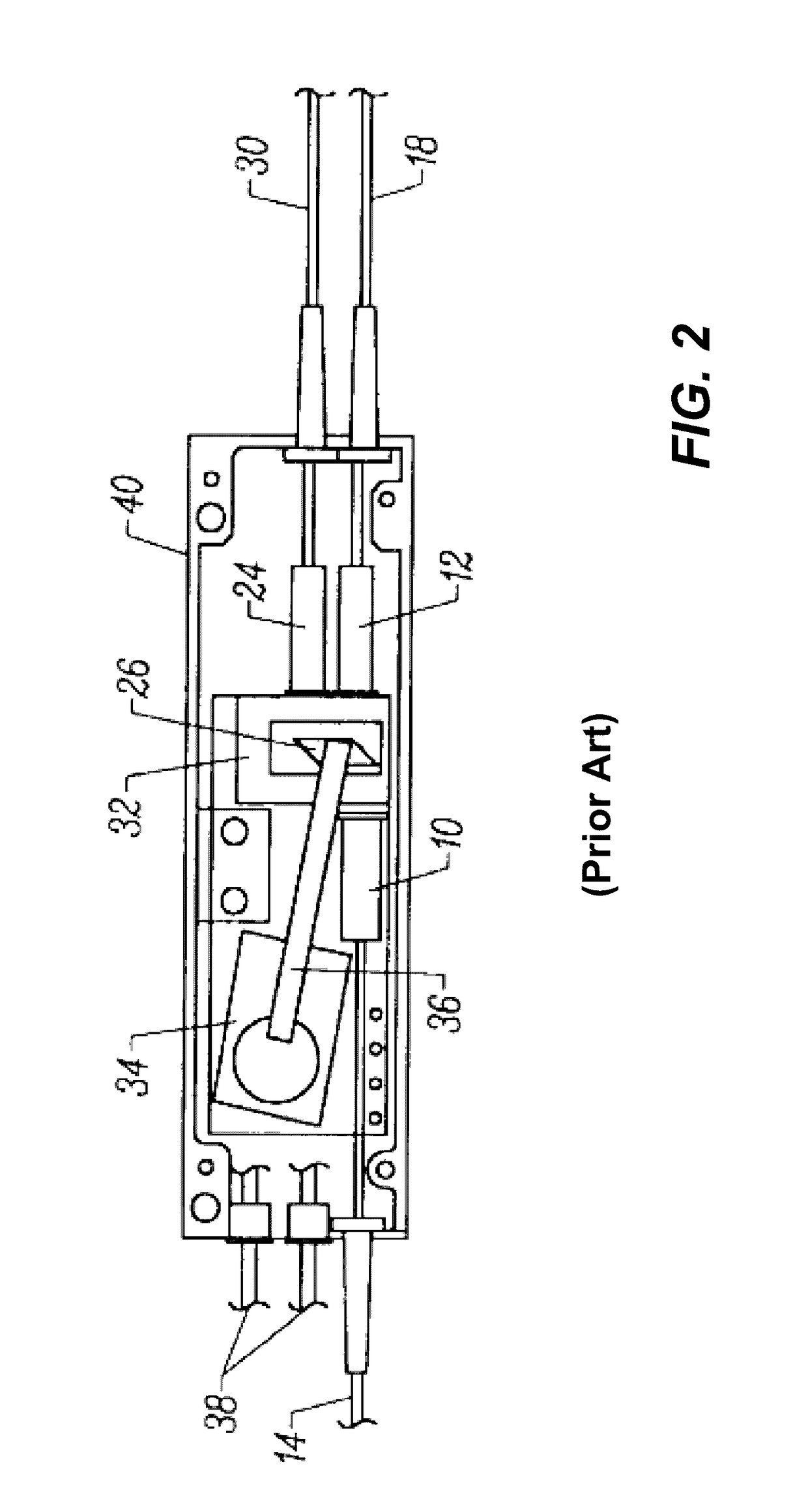
BACKGROUND OF THE INVENTION[0001]Field of the Invention[0002]The invention is generally related to the area of optical communications. In particular, the invention is related to fiber optical switch assembly, and techniques for packaging such an optical switch.[0003]The Background of Related Art[0004]Optical switches are critical building blocks in fiber optical communication networks and other applications. In optical telecommunication, an optical switch is a switch that enables signals in optical fibers to be selectively switched from one end to another. Electromechanical optical switch is one of the commonly used types. It is operated by moving either the ends of input fibers relative to the ends of output fibers, or a mirror / prism to redirect optical signals to a selected output fiber without moving the optical fibers themselves.[0005]Moving a prism is one technique to build a fiber optic switch. As shown in FIG. 1, a prism 102 is employed to switch a light beam, namely an optic...

Claims


Application Information

Patent Timeline
Patent Type & Authority Patents(United States)
IPC IPC(8): G02B6/35G02B6/36G02B6/42
CPCG02B6/3616G02B6/3528G02B6/355G02B6/3582G02B6/4239G02B6/4231G02B6/3636G02B6/32G02B6/3556G02B6/3558
Inventor WANG, XINZHONGLI, YAO
Owner ALLIAN FIBER OPTIC PROD INC
Why Eureka
Try Eureka