
Methods and apparatuses of lens flare rendering using linear paraxial approximation, and methods and apparatuses of lens flare rendering based on blending

a technology of linear paraxial approximation and lens flare, applied in image enhancement, texturing/coloring, image analysis, etc., can solve the problems of large computation load on a complicated optical system, difficult real-time use of methods, undesired patterns of sensors, etc., to achieve high speed, reduce speed, and speed up speed

Active Publication Date: 2017-03-14
RES & BUSINESS FOUND SUNGKYUNKWAN UNIV
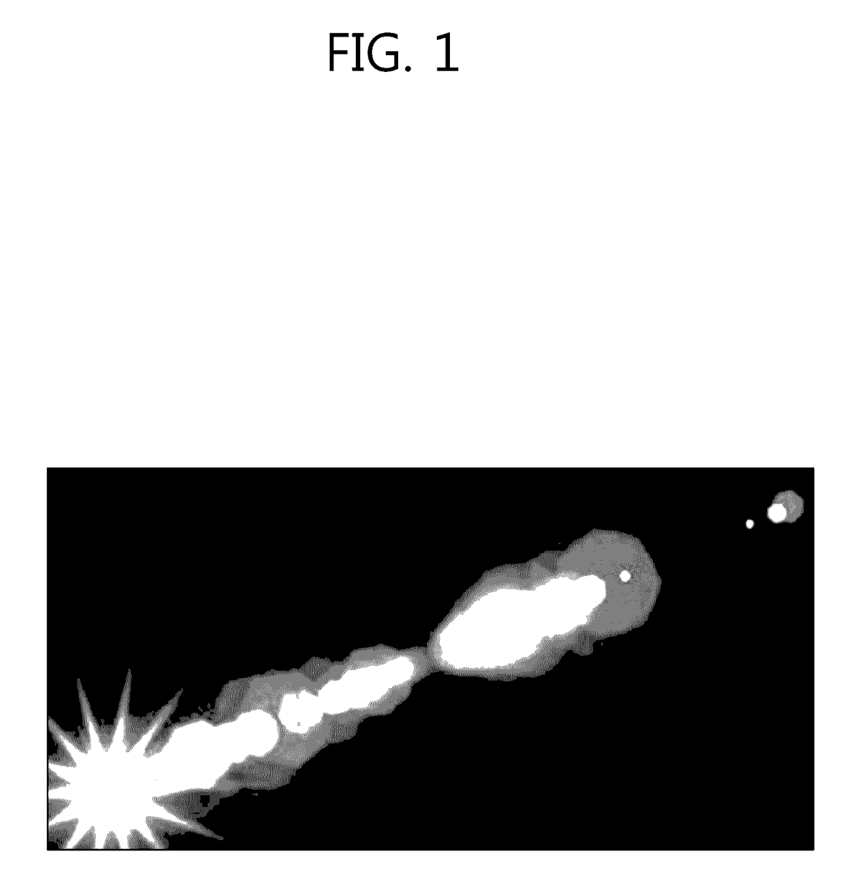
View PDF3 Cites 0 Cited by
  • Summary
  • Abstract
  • Description
  • Claims
  • Application Information

AI Technical Summary

Benefits of technology

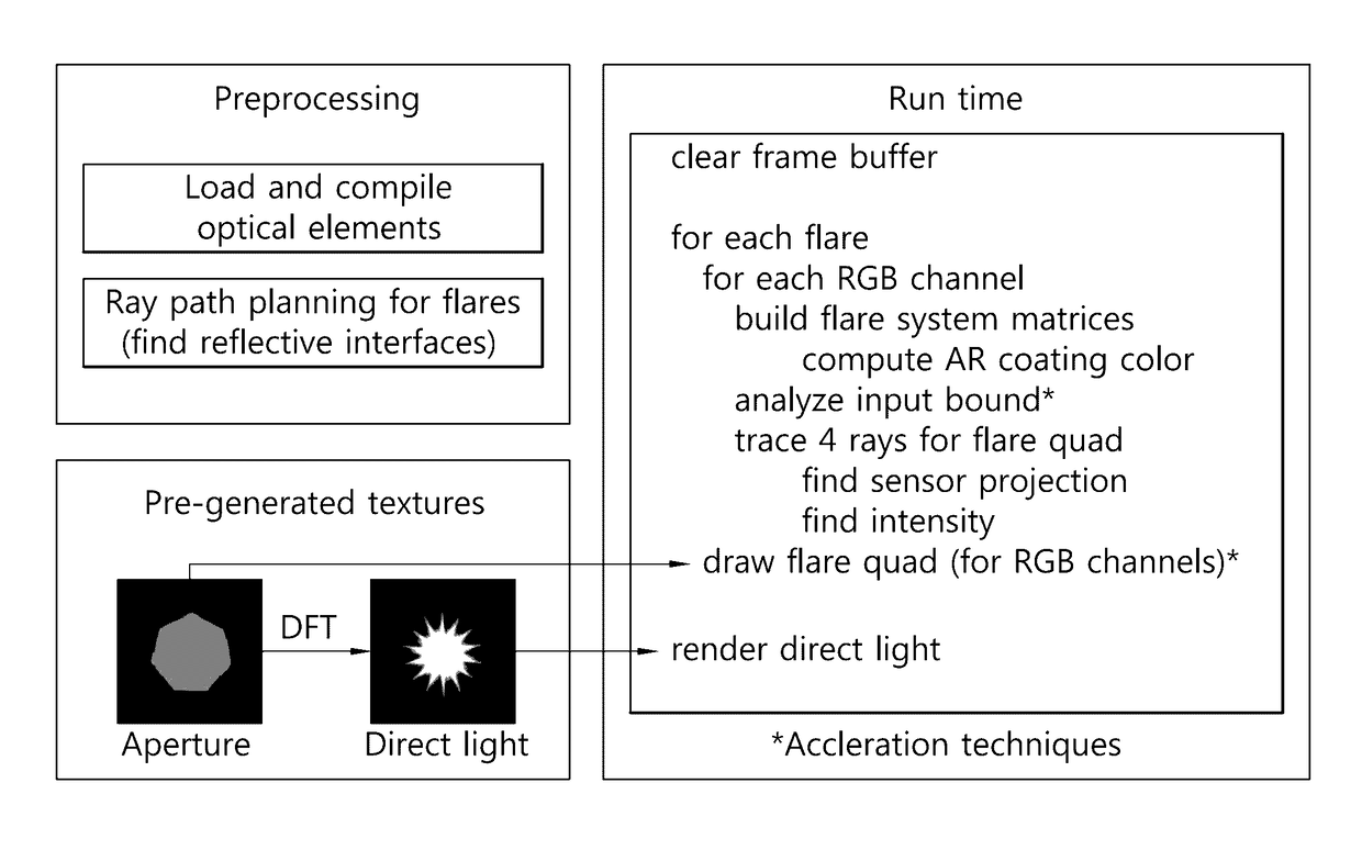
[0008]To overcome the above-described objects, an object of the present invention is to provide a method and apparatus of generating a lens flare, which quickly and effectively simulates sprites using physical characteristics of a lens system to create a more precise lens flare rendering result.
[0009]Further, an object of the present invention is to provide a blending-based lens flare rendering method and apparatus that may generate a lens flare including a non-linear pattern as well as a linear pattern in real-time applications.
[0053]Further, according to another embodiment of the present invention, a blending-based lens flare rendering method and apparatus adds non-linear effects to linear pattern-based lens flare effects, so that a lens flare may be generated reflecting most of physical characteristics created from a lens system. Nonetheless, use of a pre-recorded non-linear pattern allows for generation of a lens flare having similar quality to that obtained by the conventional light ray tracking-based simulation at a higher speed than the conventional techniques without reducing speed.

Problems solved by technology

However, light trajectory may be changed by reflection on the interface in the lens, and even-numbered light reflections would cause the sensor to have an undesired pattern.
Such a method may provide for securing of a very high-quality image, but suffers from a very large computation load on a complicated optical system.
Thus, the method is hard to use in real-time.
Rendering in the methods is enough to provide a real-time performance, but consumes lots of time in designing and is complicated and difficult.
Moreover, Such a methods take little consideration of actual physical models for lenses, causing objects to be viewed unrealistically.

Method used


Image

  • Methods and apparatuses of lens flare rendering using linear paraxial approximation, and methods and apparatuses of lens flare rendering based on blending
  • Methods and apparatuses of lens flare rendering using linear paraxial approximation, and methods and apparatuses of lens flare rendering based on blending
  • Methods and apparatuses of lens flare rendering using linear paraxial approximation, and methods and apparatuses of lens flare rendering based on blending

Examples


Embodiment Construction

[0074]Various modifications may be made to the present invention and the present invention may have a number of embodiments. Specific embodiments are described in detail with reference to the drawings. However, the present invention is not limited to specific embodiments, and it should be understood that the present invention includes all modifications, equivalents, or replacements that are included in the spirit and technical scope of the present invention.

[0075]The terms “first” and “second” may be used to describe various components, but the components are not limited thereto. These terms are used only to distinguish one component from another. For example, the first component may be also named the second component, and the second component may be similarly named the first component. The term “and / or” includes a combination of a plurality of related items as described herein or any one of the plurality of related items.

[0076]When a component is “connected” or “coupled” to another...


PUM


Abstract

A lens flare generation method and apparatus simulates lens flare effects through paraxial approximation-based linear approximation to generate a lens flare utilizing physical characteristics of a lens system while generating a lens flare at high speed. A non-linear effect may be added to a linear pattern-based lens flare effect to generate an actual lens flare reflecting most of physical characteristics generated from the lens system. A pre-recorded non-linear pattern may be used.

Description

CROSS-REFERENCE TO RELATED APPLICATION[0001]This application claims priority to Korean Patent Application No. 10-2013-0108389 filed on Sep. 10, 2013 and No. 10-2014-0073605 filed on Jun. 17, 2014, the contents of which are herein incorporated by reference in its entirety.BACKGROUND[0002]Field[0003]The present invention relates to methods of generating optical effects, and more specifically, to methods of generating lens flare effects.[0004]Description of Related Art[0005]Lens flare is caused by an undesired light reflection in an optical system. Lens flare occurs when light rays passing through the optical system are reflected towards an unintended direction by the lens surface. A lens is designed to refract incident light to reach a sensor. However, light trajectory may be changed by reflection on the interface in the lens, and even-numbered light reflections would cause the sensor to have an undesired pattern. This is called “lens flare.” A flare pattern caused by a single even-nu...

Claims


Application Information

Patent Timeline
Patent Type & Authority Patents(United States)
IPC IPC(8): G06T15/50
CPCG06T15/50G06T5/005G06T5/50G06T11/001G06T15/503G06T2207/20216
Inventor LEE, SUNG KIL
Owner RES & BUSINESS FOUND SUNGKYUNKWAN UNIV
Learn More