Flow sensor and method

Active Publication Date: 2017-03-21
EVENT MEDICAL
View PDF14 Cites 2 Cited by
  • Summary
  • Abstract
  • Description
  • Claims
  • Application Information

AI Technical Summary

Benefits of technology

[0015]In the illustrated embodiments, the principles of the disclosure are applied to a fixed orifice flow sensor; however, they can also be applied to a variable orifice flow sensor by providing movable or adjustable obstructions in the flow pathway. In the present disclosure, the obstructions may comprise one or more of a geometric obstruction, a diametric obstruction, or a surface or boundary layer obstruction. In addition, the obstructions may be such that a venturi effect is induced in only a portion of the orifice or flow pathway, particularly that portion where the pressure ports are located. In other portions of the flow pathway, no venturi effect is induced or a relatively small effect is induced. In the illustrated embodiments, the obstructions which provide the venturi effect are desirable in one portion of the flow pathway but relatively less desirable in another portion of the flow pathway. These obstructions can be provided in both a cross-sectional dimension as well as a longitudinal dimension along the flow pathway. In a cross-sectional sense, the obstructions

Problems solved by technology

However, the resistance generated by the flow sensor, and the resulting increase in pressure, increases the work or effort that the patient must exert in order to breath.
However, if the resistance is too great, or if the pressure drop is too large, the patient must exert a greater effort in breathing.
However, if the resistance is reduced, in order to reduce the patient's effort at larger flow rates, that same orifice may not generate sufficient pressure drop at lower flow rates

Method used


Image

  • Flow sensor and method
  • Flow sensor and method
  • Flow sensor and method

Examples


Embodiment Construction

[0036]The following description of certain embodiments of the present disclosure are illustrative only and in accordance with the Figures referenced below. Persons of ordinary skill will recognize that other embodiments are within the scope of this disclosure and that this invention is not to be limited by the embodiments illustrated and described, but by the appended claims, and any future claims supported by this specification, whether issued in connection with this initial application or a future related application. Moreover, multiple embodiments are indeed described herein and illustrated in the drawings; thus confirming that various embodiments are within the scope of this disclosure.

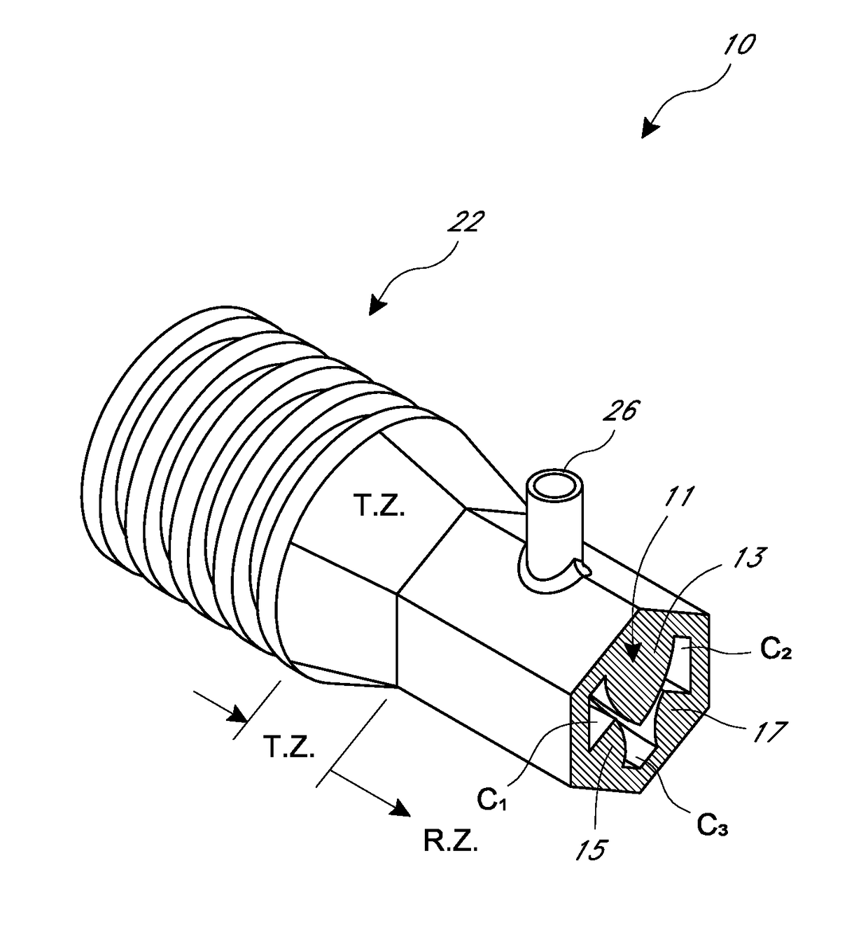
[0037]Some of the important advantages of the present flow sensor can be generally described as follows: At higher flow rates, the sensor exhibits a lower pressure drop in order to reduce the patient's effort in breathing. At the same time, for the same sensor having the same resistance profile an...


PUM


Abstract

A fluid flow sensor for use in measuring flow parameters in gas and other fluid applications, including patient ventilators and the like. The sensor is characterized by a lower pressure drop at higher flow rates in order to minimize patient effort in breathing.

Description

BACKGROUND[0001]Field[0002]The present disclosure relates to an apparatus and method for determining the flow rate of a gas or liquid (e.g. any fluid) through an orifice. Certain embodiments relate to a sensor for determining flow rate through a fixed orifice positioned within a conduit or other flow path. Other embodiments could be applied to variable orifice devices. In one embodiment, the flow sensor is situated in the inhalation and exhalation circuit of a ventilator used in the breathing therapy of a patient.[0003]Description of the Related Art[0004]In current flow sensors, a resistance or obstruction is placed in the flow path in order to create a pressure differential. This pressure differential, or pressure drop, is used to calculate flow rate through the orifice placed in the flow path. However, it is currently believed that a high degree of resistance or obstruction is necessary in order to maximize the pressure drop in the flow path, thereby providing greater accuracy in ...

Claims


Application Information

Patent Timeline
IPC IPC(8): G01F1/37G01F1/44A61M16/00A61M16/08
CPCA61M16/0858A61M16/0057A61M16/0003G01F1/44A61M2016/0036A61M2205/3331A61M2202/0208
Inventor INOUE, KOSUKEVAN DEN BERG, TEUNISNGUYEN, BICHCASTILLO, BONNIEVON
Owner EVENT MEDICAL
Why Eureka
Try Eureka