
Vehicle lavatory

a technology for lavatory and toilet, which is applied in the field of vehicle lavatory, can solve the problems of inefficiency of lavatory comprising both toilets and urinals in view of low space consumption, and achieve the effect of wide floor area, high comfort standard and use value of lavatory

Active Publication Date: 2017-03-21
AIRBUS OPERATIONS GMBH
View PDF34 Cites 2 Cited by
  • Summary
  • Abstract
  • Description
  • Claims
  • Application Information

AI Technical Summary

Benefits of technology

The present invention provides a vehicle lavatory, particularly an aircraft lavatory, with a urinal unit that can be reduced in width without compromising its comfort and use value. The urinal unit is designed with an inclined urinal opening plane and a washstand front edge opposite to the sanitary wall section, allowing users to access it from a standing position. The washstand unit also has a washstand side panel extending from its top plate downwards and parallel to the central vertical axis, forming a continuous transition to the urinal side panel. The lavatory can be used for various purposes such as washing hands, changing clothes, or putting up makeup. The washstand and urinal units can be easily removed independently from the sanitary wall section for maintenance or upgrade purposes. A lid element is pivotally mounted to the urinal, which can be opened and closed to inhibit unpleasant smell and appearance of the urinal as well as germs escaping from its interior.

Problems solved by technology

So far, lavatories comprising a urinal are considerably uncommon in aircraft construction, as lavatories merely comprising a urinal and no toilet may primarily be used by male passengers and lavatories comprising both toilet and urinal would be inefficient in view of desired low space consumption.

Method used


Image

  • Vehicle lavatory
  • Vehicle lavatory
  • Vehicle lavatory

Examples


first embodiment

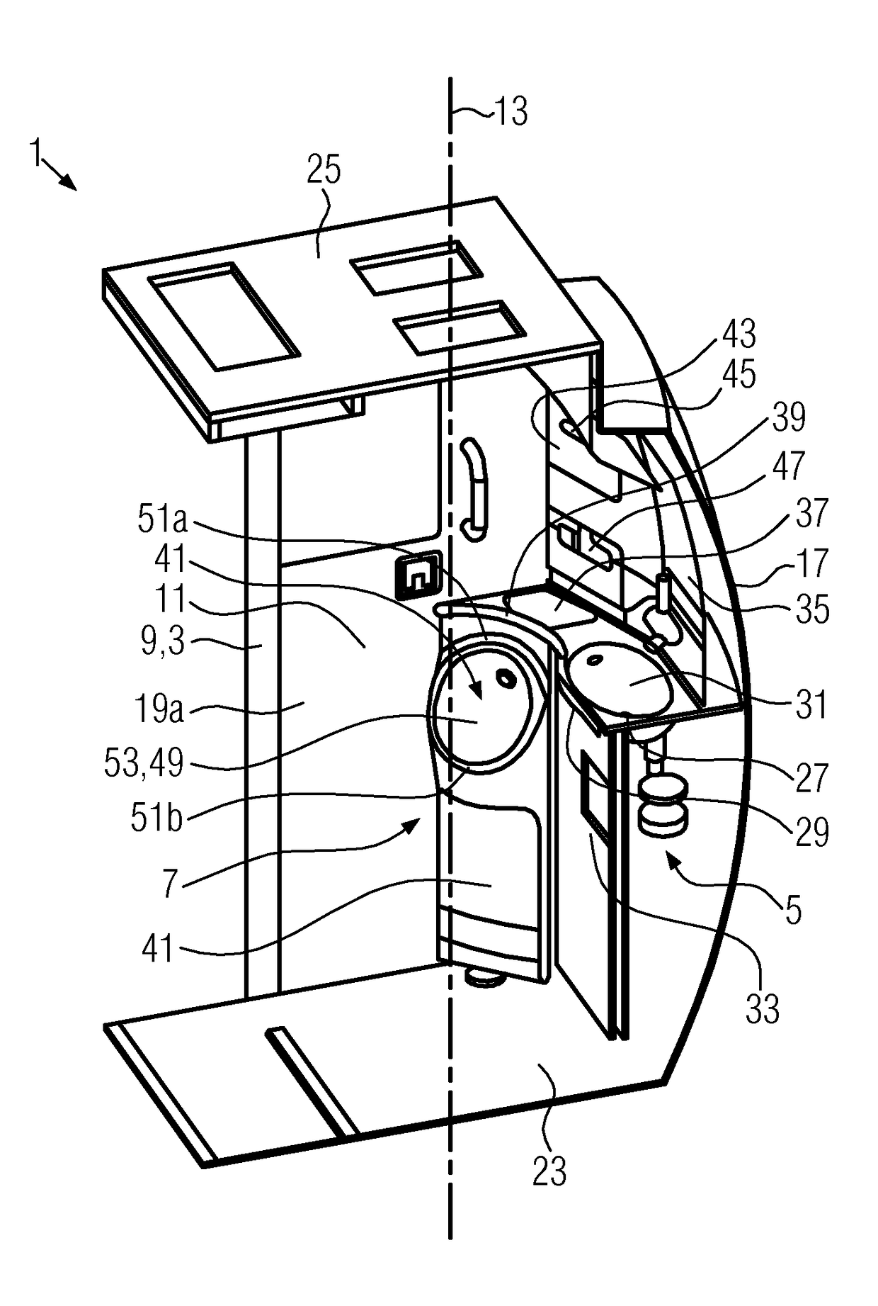
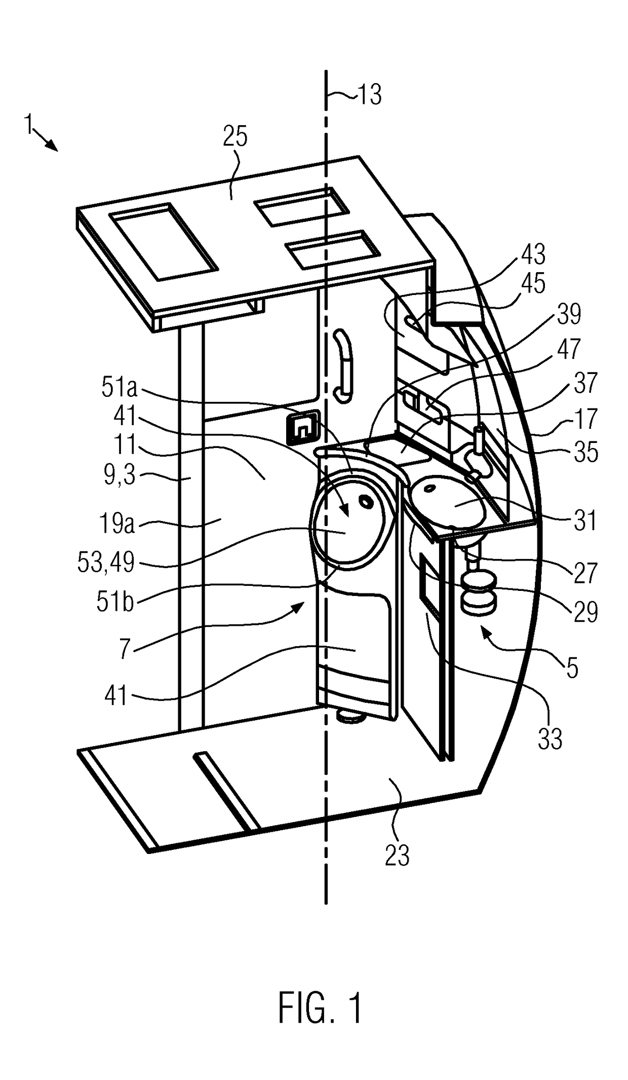
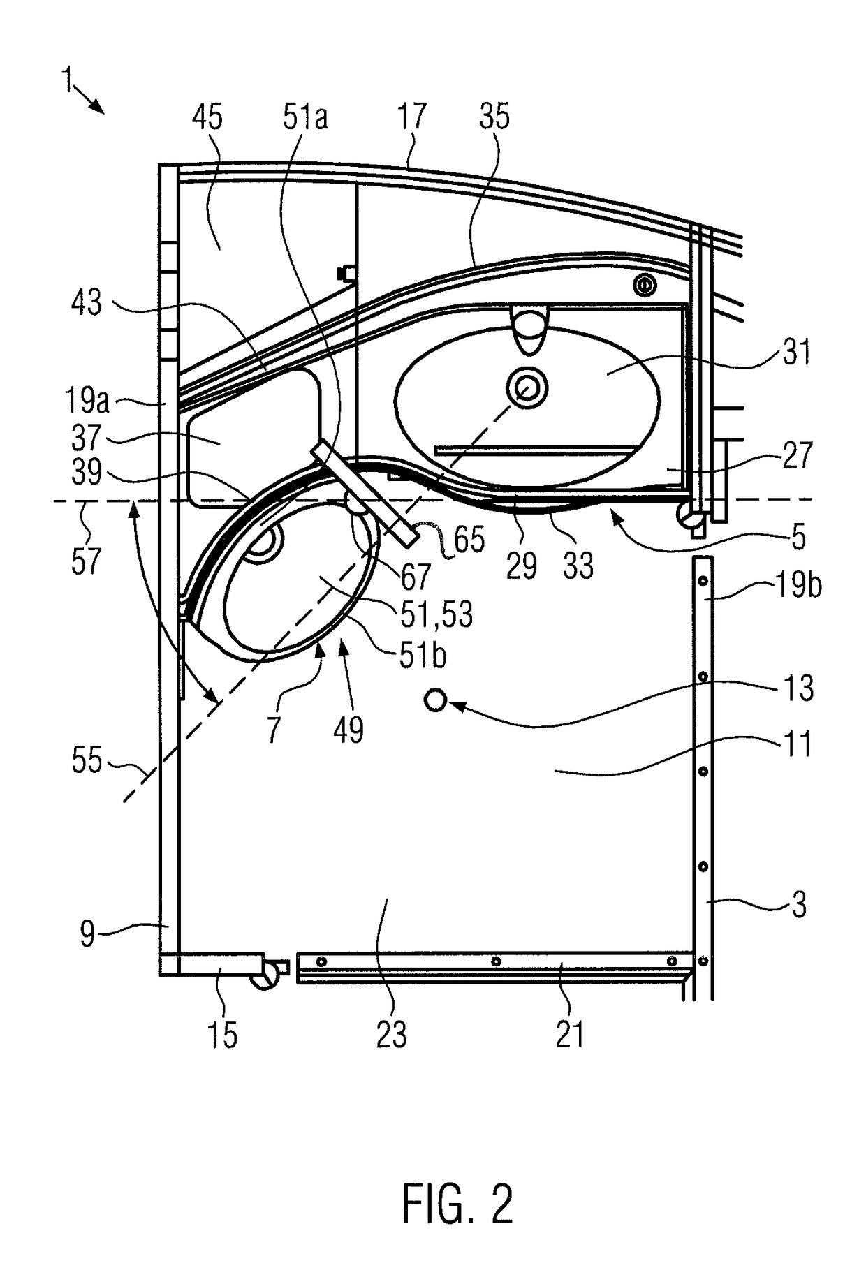
[0036]In FIGS. 1 and 2 a vehicle lavatory 1 according to the present invention is illustrated wherein this embodiment is adapted to be used in an aircraft. However, the invention is not limited to such a use of the lavatory but can be employed in buses or other vehicles.

[0037]The vehicle lavatory 1 comprises a cabin 3, a washstand unit 5, and a urinal unit 7. The cabin 3 has a circumferential wall 9 defining a cabin interior space 11 which extends about a central vertical axis 13 perpendicularly to the floor of the cabin. The circumferential wall 9 has an entrance wall section 15 (hidden in FIG. 1, see FIG. 2), a sanitary wall section 17 opposite to the entrance wall section 15, and two side wall sections 19a, 19b perpendicular to said entrance wall section 15 and said sanitary wall section 17, i.e. parallel to one another. The entrance wall section 15 includes an entrance door 21 for entering and exiting the cabin 3. The entrance wall section 15 and the two side wall sections 19a, ...

second embodiment

[0048]the vehicle lavatory 1′ comprises a cabin 3 having a circumferential wall 9, a washstand unit 5 having a washstand top plate 27 including a washbasin 31, and a urinal unit 7 having a urinal 49 including a urinal opening 51 entirely disposed below a urinal top surface 37, said urinal top surface 37 in turn extending in the same plane as the washstand top plate 27.

[0049]The second embodiment of the vehicle lavatory 1′ differs from the first embodiment by the washstand front edge 29 in a horizontal plane not being curved but extending straight and perpendicular to the side wall sections 19a, 19b. Thus, according to the second embodiment the angle of 48° is not measured between a horizontal line 55 extending in the urinal opening plane 53 and a tangent 57 to a point on the washstand front edge 29 which is closest to the entrance wall section 15, but between said horizontal line 55 and said straight washstand front edge 29 itself.

[0050]Further, as shown in FIG. 3, the urinal unit 7...


PUM


Abstract

A vehicle lavatory, in particular an aircraft lavatory, is described. The lavatory includes a cabin space with a centrally located vertical axis around which a washstand and a urinal unit are located. The washstand and urinal unit are arranged to each have an approximately horizontal surface at their top, such that a person using the lavatory has a location to place personal items during use. The horizontal surfaces of the washstand and the urinal are arranged to exist in the same plane and may be a continuous surface that may additionally cross the entirety of the width of the cabin. The urinal is arranged such that a plane defining the opening of the urinal is at an angle relative to a plane defining a front surface of the washstand such that a person using the lavatory only has to turn slightly to access the urinal and the washstand.

Description

CROSS-REFERENCE TO RELATED APPLICATION[0001]This application is the U.S. national phase of International Application No. PCT / EP2013 / 059246 filed 3 May 2013, which designated the U.S. and claims priority to European Patent Application No. 12168570.5 filed 18 May 2012, and claims the benefit of U.S. Provisional Patent Application No. 61 / 648,788 filed 18 May 2012, the entire contents of each of which are hereby incorporated by reference.BACKGROUND OF THE INVENTION[0002]The present invention relates to a vehicle lavatory, in particular an aircraft lavatory, comprising a cabin and a urinal unit. The cabin has a circumferential wall surrounding a cabin interior space and defining a central vertical axis extending through said cabin interior space, wherein said circumferential wall includes an entrance wall section and a sanitary wall section spaced from said entrance wall section.[0003]In vehicle construction and in particular in aircraft construction a permanent objective is to maximize ...

Claims


Application Information

Patent Timeline
Patent Type & Authority Patents(United States)
IPC IPC(8): B64D11/02B60R15/02B61D35/00B63B29/14B60R15/04B64D11/00
CPCB64D11/02B60R15/02B60R15/04B61D35/005B63B29/14B64D2011/0046
Inventor SCHLIWA, RALFSTRASDAS, MARIA THERESIASCHUPHAUS, FLORIANSEIBT, CHRISTIAN
Owner AIRBUS OPERATIONS GMBH
Learn More