Multi-speed gearbox

a multi-speed, gearbox technology, applied in mechanical equipment, transportation and packaging, gearing, etc., can solve the problems of significant hydraulic losses, achieve the effect of improving efficiency, design complexity, and optimizing component load and installation siz

Active Publication Date: 2017-03-21
ZF FRIEDRICHSHAFEN AG
View PDF30 Cites 35 Cited by
  • Summary
  • Abstract
  • Description
  • Claims
  • Application Information

AI Technical Summary

Benefits of technology

[0016]The object of the present invention is to propose a multi-stage transmission of the initially described type, which has nine forward gears and a reverse gear having a sufficient transmission ratio, in which the design complexity, the component load and the installation size are optimized, and in which efficiency is improved. In addition, the shift elements of the transmission should be easily accessible from outside, which makes it possible to install shift elements that can be actuated upon demand. In addition, the transmission should be suitable for standard design and for a frontal transverse design.
[0023]Because the first, second and third clutches are disposed on the drive shaft of the transmission and the remaining shift elements are designed as brakes, good accessibility of all the shift elements of the transmission is ensured, as a result of which the shift elements may be designed as shift elements that can be actuated upon demand. Within the context of further embodiments, shift elements of the transmission may be designed, inter alia, as shift elements that can be hydraulically actuated.
[0024]In addition, transmission ratios are attained that are especially suitable for passenger vehicles, as well as a greater overall gear ratio of the multi-stage transmission, which results in improved driving comfort and a significant reduction in fuel consumption.
[0025]Furthermore, design complexity is significantly reduced with the multi-stage transmission, according to the invention, due to a small number of shift elements. Using the multi-stage transmission according to the invention, it is advantageously possible to perform a start-up using a hydrodynamic converter, an external start-up clutch, or any other suitable external start-up element. It is also conceivable to perform a start-up using a start-up element integrated in the transmission. Preferably, a shift element that is actuated in the first forward gear and in the reverse gear is suitable for this.
[0026]Moreover, the multi-stage transmission, according to the invention, results in good efficiency in the main drive gears with respect to drag losses and gearing losses.
[0027]Low torques are advantageously present in the shift elements and in the planetary gear sets of the multi-stage transmission, thereby advantageously reducing wear in the multi-stage transmission. In addition, the low torques make it possible to utilize correspondingly low dimensions, thereby reducing the necessary installation space and related costs. Furthermore, the rotational speeds of the shafts, shift elements, and planetary gear sets are low.

Problems solved by technology

According to the prior art, the shift elements of multi-stage transmission thus designed, which are usually designed as lamellar clutches or brakes, are actuated hydraulically, which disadvantageously results in significant hydraulic losses.

Method used


Image

  • Multi-speed gearbox
  • Multi-speed gearbox
  • Multi-speed gearbox

Examples


Embodiment Construction

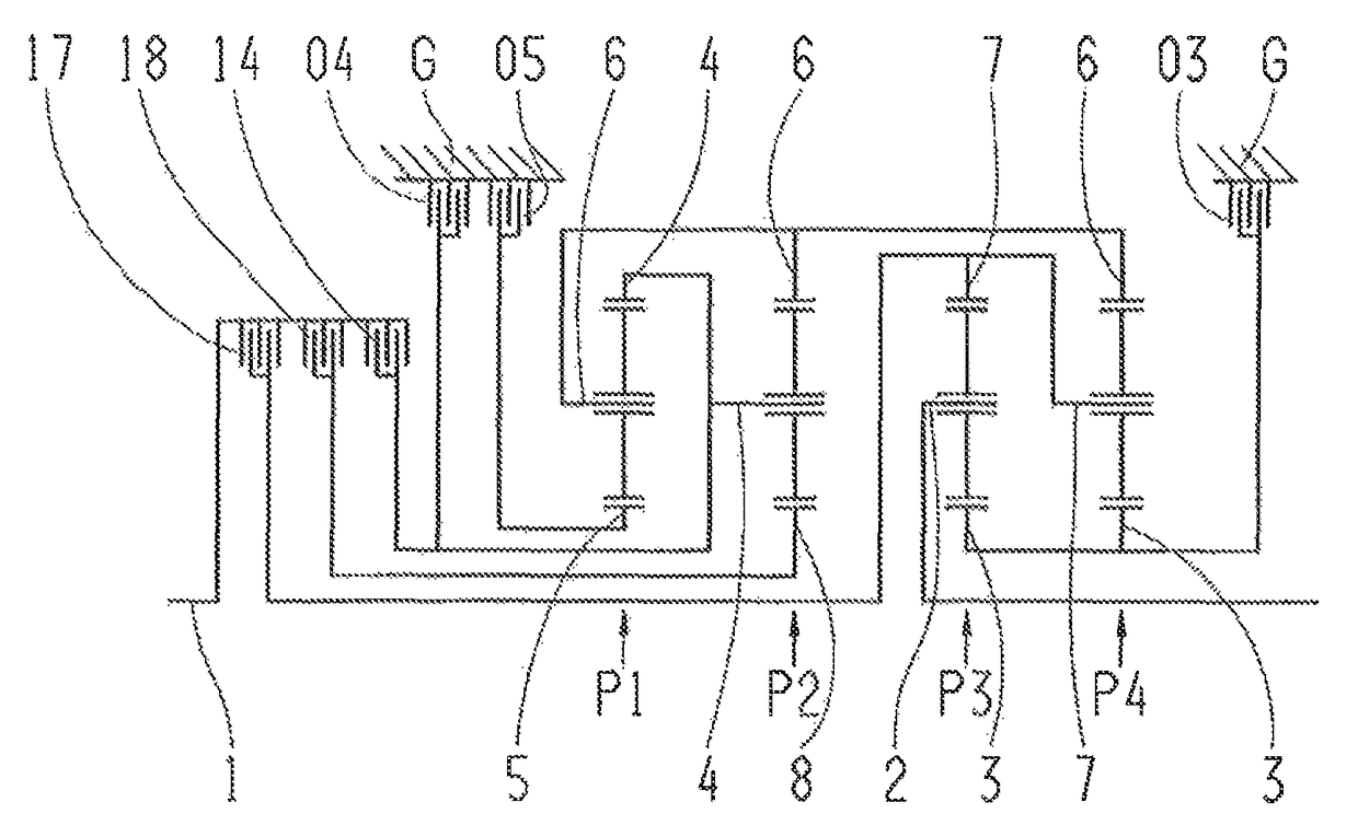
[0037]FIG. 1 shows a multi-stage transmission, according to the invention, which has a drive shaft 1, an output shaft 2, and four planetary gear sets P1, P2, P3 and P4, which are disposed in a housing G. In the example shown in FIG. 1, planetary gear sets P1, P2, P3, P4 are designed as minus planetary gear sets. According to the invention, at least one of the planetary gear sets P1, P2, P3, P4 can be implemented as a plus planetary gear set if the carrier and ring gear connection are exchanged and, simultaneously, the value of the stationary transmission ratio is increased by 1 in comparison to the embodiment as a minus planetary gear set.

[0038]In the embodiment shown here, viewed axially, the planetary gear sets P1, P2, P3, P4 are disposed in the sequence of the first planetary gear set P1, the second planetary gear set P2, the third planetary gear set P3, and the fourth planetary gear set P4. According to the invention, the axial sequence of the individual planetary gear sets and ...


PUM


Abstract

The multi-stage transmission comprises four planetary gear sets, eight rotatable shafts and six shift elements. Sun of first set is connected to fifth shaft which is couplable, via third brake, to housing. Drive shaft is connectable, via first clutch, to fourth shaft connected to ring of first set and carrier of second set and which is couplable, via second brake, to housing. Drive shaft is connectable, via second clutch, to seventh shaft connected to carrier of fourth set and ring of third set and is connectable, via third clutch, to eighth shaft connected to sun of second set. Sixth shaft is connected to carrier of first set, ring of second set and ring of fourth set. Third shaft is connected to sun of third set and sun of fourth set and is couplable, via first brake, to housing. Drive shaft is connected to carrier of third set.

Description

[0001]This application is a National Stage completion of PCT / EP2013 / 055076 filed Mar. 13, 2013, which claims priority from German patent application serial no. 10 2012 206 819.8 filed Apr. 25, 2012.FIELD OF THE INVENTION[0002]The present invention relates to a multi-stage transmission of a planetary design, in particular an automatic transmission for a motor vehicle.BACKGROUND OF THE INVENTION[0003]According to the prior art, automatic transmissions, particularly for motor vehicles, comprise planetary gear sets that are shifted using friction elements or shift elements such as clutches and brakes, and typically are connected to a start-up element, such as a hydrodynamic torque converter or a fluid coupling, that is subject to a slip effect and is provided optionally with a lock-up clutch.[0004]Such an automatic transmission is known, for example, from DE 199 12 480 B4 by the applicant. It comprises three single-carrier planetary gear sets, as well as three brakes and two clutches fo...

Claims


Application Information

Patent Timeline
Patent Type & Authority Patents(United States)
IPC IPC(8): F16H3/66F16H3/44
CPCF16H3/66F16H2003/445F16H2200/0065F16H2200/2012F16H2200/2046F16H2200/2064F16H2200/2094
Inventor BECK, STEFANSIBLA, CHRISTIANRIEGER, WOLFGANG
Owner ZF FRIEDRICHSHAFEN AG
Why Eureka
Try Eureka