
Double flap valve with quick-change replaceable wear surface

a technology of wear surface and flap, which is applied in the field of flapgate valves, can solve the problems of small air leakage, affecting the sealing and destroying the ability of the seat and flap to form an airtight seal, etc., and achieves the effect of quick and efficient replacemen

Active Publication Date: 2017-03-21
PLATTCO
View PDF18 Cites 0 Cited by
  • Summary
  • Abstract
  • Description
  • Claims
  • Application Information

AI Technical Summary

Benefits of technology

[0011]The inventors have also discovered that due to machining tolerances associated with metal surfaces used in conventional seats and flaps, the resulting seal is not completely airtight and has small air leaks due to gaps between the seat and flap that are a few thousandths of an inch. In high-pressure pneumatic conveying applications, small particles pass through these gaps at high velocity, enlarging the gaps, and causing the valve to fail in a short time period. Instead of taking the flap-gate valve assembly apart and replacing an entire seat and / or flap, or regrinding the surfaces thereof, the presently disclosed subject matter includes a replaceable wear surface for quickly swapping out a worn-out surface with a new one. Further, the replaceable wear surface may be made from abrasion-resistant material, such as ceramic or tungsten carbide, or a combination thereof. In certain embodiments that employ a combination of ceramic and tungsten carbide, tungsten carbide is located on portions of the replaceable wear surface that experience a direct impact when the flap-gate valve closes, while the ceramic is located on portions that do not encounter direct impact. This arrangement is advantageous because tungsten carbide can withstand impact and will not fracture, whereas ceramic is less expensive but will fracture more easily than tungsten carbide. The ceramic, tungsten carbide, or combination thereof, is vacuum bonded or fastened with epoxy to a corresponding surface, disclosed below.
[0013]In either case, the material selected in accordance with the present invention for the replaceable wear surface extends the life of the wear surface of the present invention beyond that of conventional nickel alloy or other metal surfaces used in the seats and / or flaps of conventional flap-gate valves.
[0052]engaging all screws and bolts with the new seat, thereby securing the new seat in place in the flap-gate valve;
[0060]engaging all screws and bolts with the new seat, thereby securing the new seat in place in the flap-gate valve;

Problems solved by technology

Particulates, especially abrasive ones, wear away at this area of the seat and flap while flowing through the opening in the seat.
Eventually, this destroys the ability for the seat and flap to form an airtight seal.
The inventors have also discovered that due to machining tolerances associated with metal surfaces used in conventional seats and flaps, the resulting seal is not completely airtight and has small air leaks due to gaps between the seat and flap that are a few thousandths of an inch.
In high-pressure pneumatic conveying applications, small particles pass through these gaps at high velocity, enlarging the gaps, and causing the valve to fail in a short time period.

Method used


Image

  • Double flap valve with quick-change replaceable wear surface
  • Double flap valve with quick-change replaceable wear surface
  • Double flap valve with quick-change replaceable wear surface

Examples


Embodiment Construction

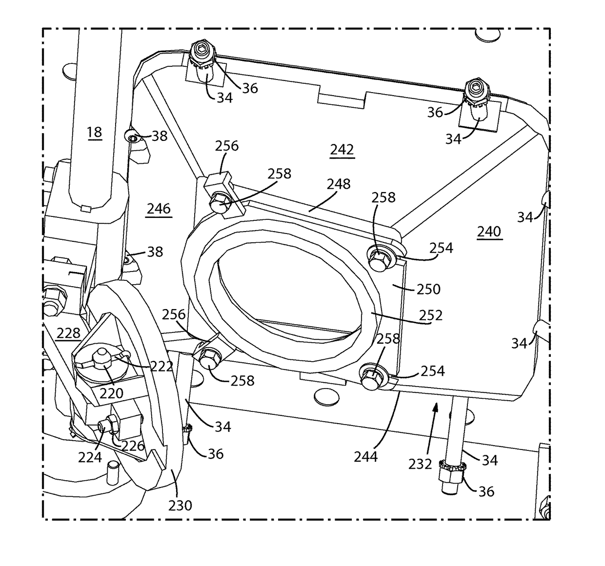
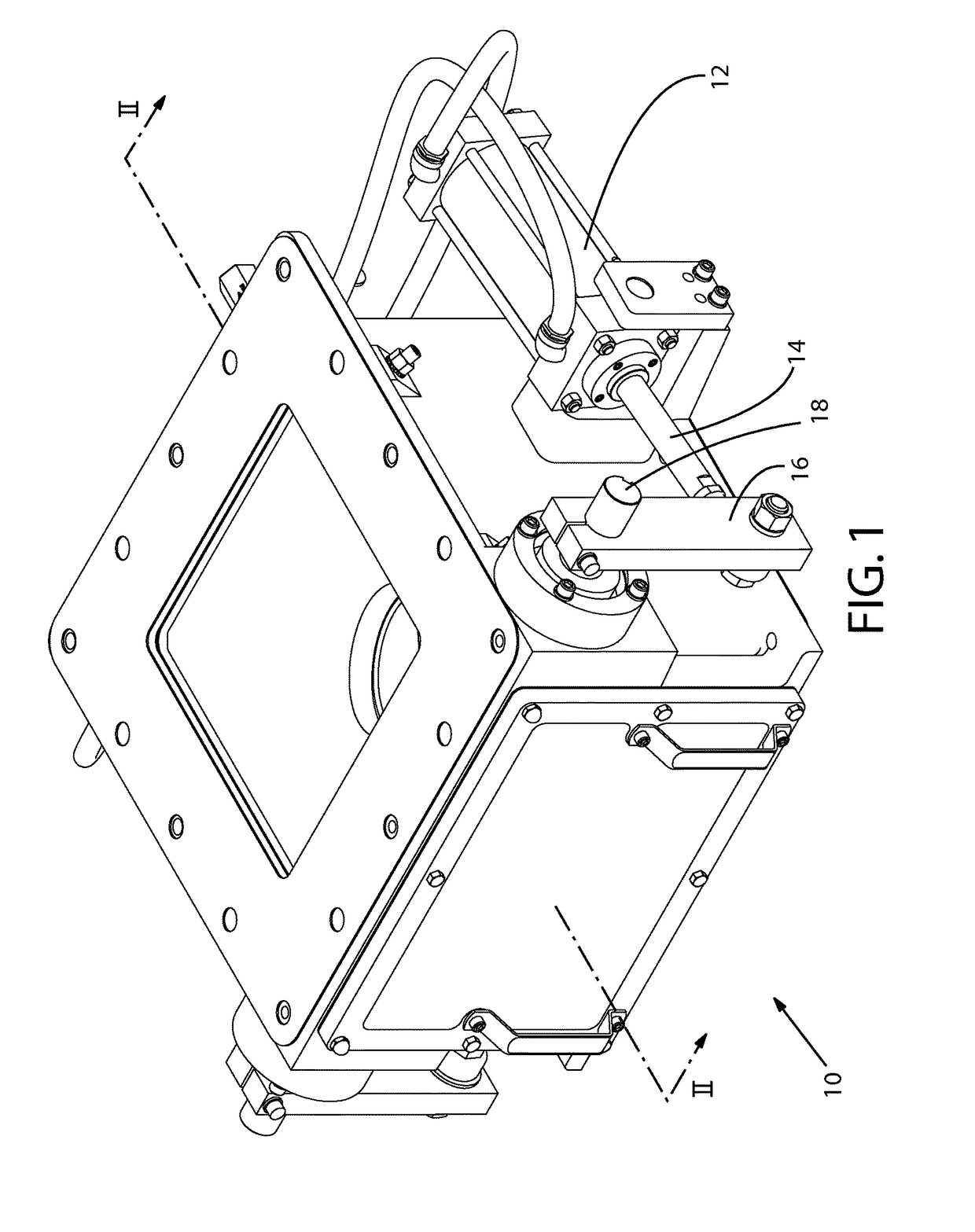
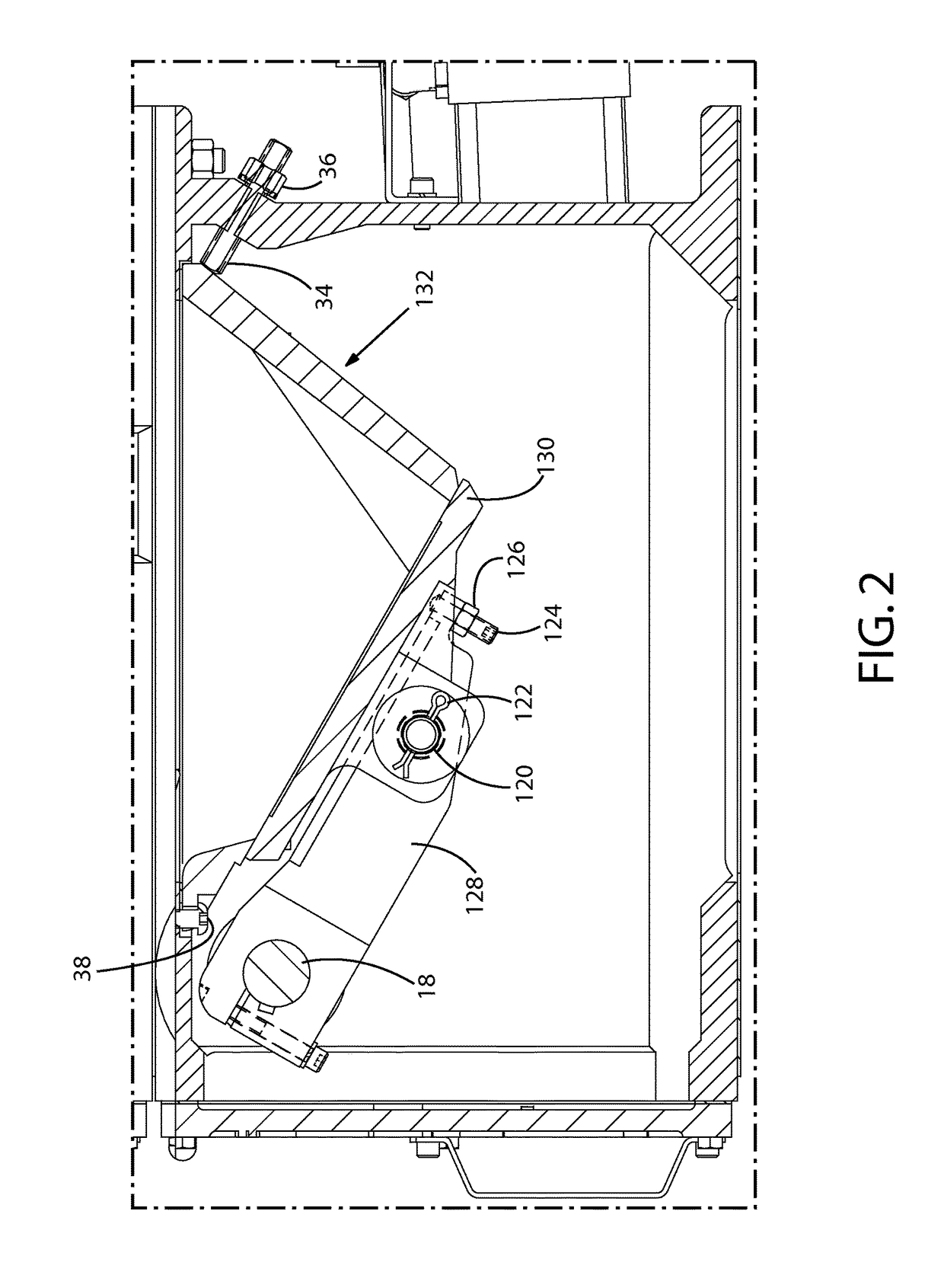
[0081]This discussion relates to an exemplary flap-gate valve which can house prior-art components OR components adapted to work in conjunction with a replaceable wear surface, in accordance with the present invention. Indeed, the ability to retrofit an existing flap-gate valve to include components in accordance with the present invention is an important feature hereof. Throughout the description of FIGS. 1 through 7, which relate to a first style of flap-gate valve, items referred to with a two-digit number are common across the figures. They refer to components of the flap-gate valve that remain the same, while other components change from prior art components (labeled in a 1xx format) to components adapted to work in conjunction with a replaceable wear surface (labeled in a 2xx format). Throughout the description of FIGS. 8 through 14, which relate to another style of flap-gate valve, items referred to in the 3xx format refer to components of that style flap-gate valve that are ...


PUM


Abstract

A flap-gate valve having a replaceable wear surface, methods of replacing a wear surface with a replacement wear surface, and methods of retrofitting an existing flap-gate valve with components adapted to work in conjunction with a replaceable wear surface.

Description

TECHNICAL FIELD[0001]The present disclosed subject matter relates to valves and more particularly to flap-gate valves for use in pneumatic conveying in an industrial environment.BACKGROUND[0002]Flap-gate valves are used in industrial settings to transport dry particulate matter. Essentially, they comprise a mechanical arm, pivotally mounted at one end and having a flap (also sometimes referred to herein as a “flapper”) affixed to the other end. The arm rotates to move the flap into and out of engagement with the bottom opening of a structure known as a seat. When the flap is not engaged with the seat, any particulates in the seat are free to flow through the bottom opening. When the flap engages with the bottom opening of the seat, a seal is formed, preventing the contents of the seat from passing through the bottom opening. In other words, the seat is essentially a temporary receptacle with an opening at the top for receiving particulate matter, and a bottom which is open when the ...

Claims


Application Information

Patent Timeline
Patent Type & Authority Patents(United States)
IPC IPC(8): F16K3/00F16K1/20F16K3/04
CPCF16K1/2057F16K1/2007F16K3/04Y10T137/0514
Inventor SURPRENANT, DEANGUAY, KEVIN
Owner PLATTCO
Learn More