Portable device to limit unwanted movement of drums and other musical instruments

Pending Publication Date: 2021-06-17
BUTERA WILLIAM JAMES +1
View PDF2 Cites 0 Cited by
  • Summary
  • Abstract
  • Description
  • Claims
  • Application Information

AI Technical Summary

Benefits of technology

The present invention is a device that prevents musical instruments from moving on the floor during use. It is independent from the instrument, not attached to it, and can be easily installed and uninstalled. It is lightweight, compact, and portable. It uses a downward-facing gripping surface that grabs onto the floor to restrict movement. It is used with various instruments and does not damage them or the floor. It also has no moving parts and does not need tools or assembly. The device can be used on instruments of varying shapes, sizes, and weights. It also has a rear-facing surface that transfers the kinetic energy from the instrument to the downward-facing gripping surface. Overall, the device prevents musical instruments from moving and promotes stability and safety during use.

Problems solved by technology

However, during use, musicians must apply considerable force to the instrument, which can cause the instrument to move in unwanted directions.
This unwanted movement of the musical instruments is a problem for musicians.
Because musicians depend on muscle memory in order to consistently play their instruments, when the position of their instrument shifts during a performance, their ability to play is impaired, and the quality and sound of their performance is diminished.
It is also disruptive for the musician to have to attempt to reconfigure their instrument setup during a performance.
However, such method has numerous drawbacks for the musician.
The objects are extremely heavy, difficult to transport, hard to move or reposition, and they are unsightly in a performance setting.
And we have noticed that one cinder block is not adequate to stabilize a drum set.
Clearly this is not practical.
And the risk of personal injury to the drummer from carrying, setting up, and transporting such heavy objects is a concern.
So large, heavy devices such as concrete blocks and sand bags are not practical gear for most musicians.
However, we have noticed that the effectiveness of these devices is less than optimal precisely because said anchoring devices are attached to the very moving instrument which they are trying to stabilize.
This attachment of the device to the instrument or its appendages means that the devices are subject to all of the vibrations, bouncing, rebounding, and chaotic forces of the musical instrument itself.
Such bouncing and rebounding forces inevitably include upward forces and motion which tend to unweight and uplift the anchoring device and as such cause it to loosen or detach its grip on the floor and thus allow the device and hence the instrument to move in unwanted directions.
In the case of the pedal-activated bass drum, we have observed that anchoring devices mounted onto either the drum rim hoops or onto appendages such as drum spurs experience the aforementioned uplifting problem and tend to lose their grip on floor surfaces resulting in unwanted movement across the floor plane.
It should be noted that the forces and motions caused by operation of musical instruments, are often complex, multi-vectored, chaotic and somewhat unpredictable.
For these reasons, devices mounted directly to the instruments they are trying to secure will tend to be dislodged from the floor and hence will allow unwanted movement of the musical instruments.
We have also noticed that devices mounted directly onto the musical instruments can damage the surface of the instrument, such as the wood hoops of the bass drum, and for this reason musicians may tend to avoid such devices.
Such an approach is impractical for most drummers because it cannot be easily removed and reinstalled in various locations as the drummer travels.
Moreover the nails, screws and bolts would permanently damage the flooring leaving holes and splinters, much to the consternation of venue owners and other performers subsequently using the venue.
As such, this approach cannot be used with blocking material that has pliable, malleable, shock-absorbing properties as may be desirable for reducing vibration, dissipating energy, and minimizing rebound of percussive forces.
This would make the system heavy, bulky, more difficult to transfort, and generally non-portable.
Also such a system would not permit relocation of the affixed board on the floor-covering material so the musician would be confined to one predetermined setup of their instruments.
Because the spacing on instrument components, such as the spacing between the bass drum and hi-hat cymbal stand vary infinitely between drummers based on physique, size, method of playing, and personal preference, any system having boards permanently affixed could not fit all drummers and would hence have commercial disadvantage.
We have observed several problems with this approach.
First, it creates a tripping hazard to have ropes, strings, or straps strung above the floor between the bass drum and the drummer's seat.
Second, during the course of a performance, drummers often need to reposition their seat for comfort, to adjust their position based on the music, and other reasons.
If the bass drum is tethered to the seat, any repositioning of the seat will inevitably cause the bass drum to move and changes its position relative to the rest of the drum set.

Method used


Image

  • Portable device to limit unwanted movement of drums and other musical instruments
  • Portable device to limit unwanted movement of drums and other musical instruments
  • Portable device to limit unwanted movement of drums and other musical instruments

Examples


Embodiment Construction

[0027]In the following detailed description, certain specific terminology will be employed and certain concepts will be referenced for the sake of clarity and a particular embodiment described in accordance with the requirements of 35 USC 112, but it is to be understood that the same is not intended to be limiting and should not be so construed inasmuch as the invention is capable of taking many forms and variations within the scope of the appended claims.

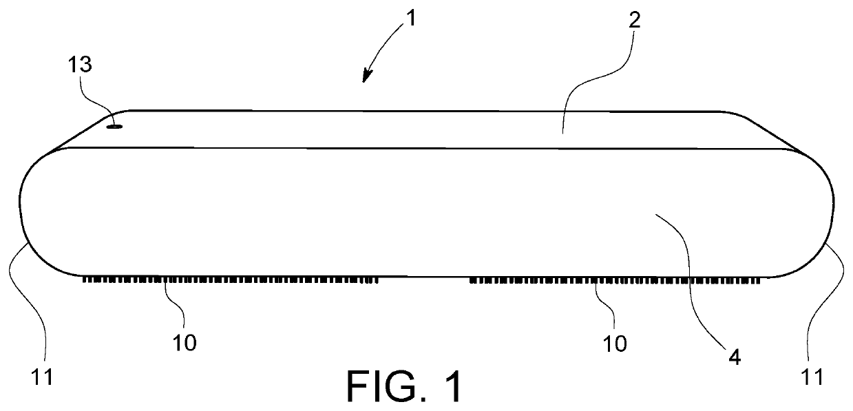
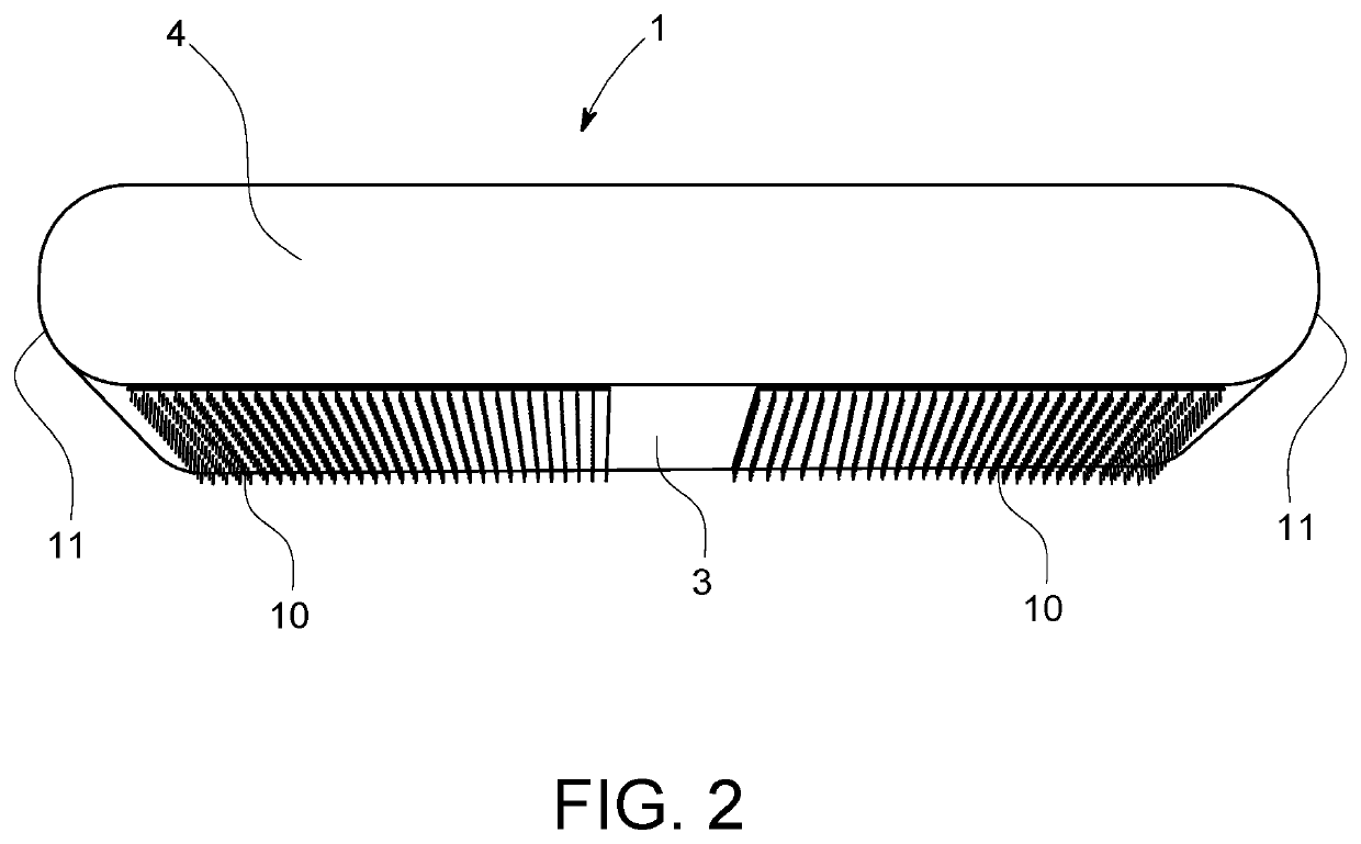
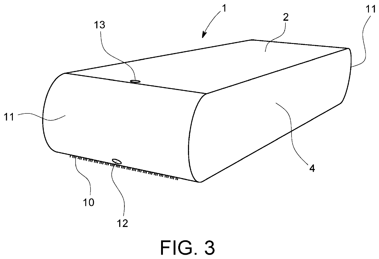
[0028]One embodiment of the musical instrument blocking device is shown in FIG. 1. The musical instrument blocking device 1 has a main body 2 which in one embodiment can be a malleable shock-absorbing material such as but not limited to rubber or EVA foam with structure and firmness sufficient to transfer kinetic energy. In this embodiment the planar rear-facing surface 4 rises perpendicularly from the bottom-facing surface 3.

[0029]The dimensions of the planar rear-facing surface are sufficient in height to contact and engage with...


PUM


Abstract

A portable musical instrument blocking device (1) to limit unwanted movement of a musical instrument during use. The blocking device engages said musical instrument's forward-facing leading edge where kinetic energy of the musical instrument's forward motion is transferred to the main body (2). A gripping material (10) on the blocking device's downward-facing surface grips the floor surface (9) and thereby limits movement on the floor plane. Engagement between the blocking device and the musical instrument is such that kinetic energy of the musical instrument's upward motion is not substantially transferred to the blocking device. The blocking device can be easily detached from the floor surface with application of manual force in the upward direction.

Description

CROSS-REFERENCE TO RELATED APPLICATIONS[0001]This application claims priority to and the benefit of U.S. Provisional Application Ser. No. 62 / 960,672 Filing Date or Jan. 13, 2020 by William James Butera and Joseph Fabbri Butera titled “A vibration-absorbing device to stop unwanted movement of objects during use for objects with curved, straight, or irregular leading edges” which prior application is incorporated by reference herein in its entirety and made part hereof.STATEMENT REGARDING FEDERALLY SPONSORED RESEARCH OR DEVELOPMENT[0002]Not ApplicableTHE NAMES OF THE PARTIES TO A JOINT RESEARCH AGREEMENT[0003]Not ApplicableSTATEMENT REGARDING PRIOR DISCLOSURES BY THE INVENTOR OR A JOINT INVENTOR[0004]The inventors represent that they have made prior disclosures of some of the concepts claimed in this application but such disclosures were made solely by the inventors and within the grace period provided in AIA 35 U.S.C. 102(a)(1).BACKGROUND OF THE INVENTION[0005]When drums and many oth...

Claims


Application Information

Patent Timeline
IPC IPC(8): G10D13/10
CPCG10D13/28G10D13/02
Inventor BUTERA, WILLIAM JAMESBUTERA, JOSEPH FABBRI
Owner BUTERA WILLIAM JAMES
Why Eureka
Try Eureka