
On-rope work positioning device

a positioning device and rope technology, applied in the field of rope ascending/descending apparatus, can solve the problems of insufficient function of traditional friction hitches and prussic knots

Active Publication Date: 2017-03-28
MERRITT ARBOREAL DESIGN INC
View PDF37 Cites 5 Cited by
  • Summary
  • Abstract
  • Description
  • Claims
  • Application Information

AI Technical Summary

Benefits of technology

The invention is a device used to securely hold ropes in place. The device has a clamp element with a ring to attach to a carabineer, and can accommodate ropes of different diameters by adjusting the distance between the roller and the fixed pin. The device also has splines to securely hold the fixed pin in place. Additionally, there is a third eccentric body that can be adjusted to compensate for ropes of different diameters. The technical effect of this device is to provide a secure and adjustable way to hold rokes in place, making it easier to handle and secure them in various situations.

Problems solved by technology

Due to the 1:1 natureof SRT, traditional friction hitches and prussic knots do not function satisfactorily.

Method used


Image

  • On-rope work positioning device
  • On-rope work positioning device
  • On-rope work positioning device

Examples


Embodiment Construction

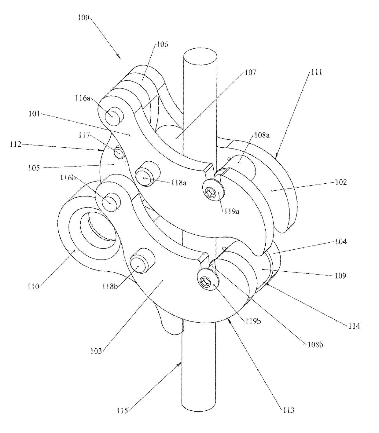
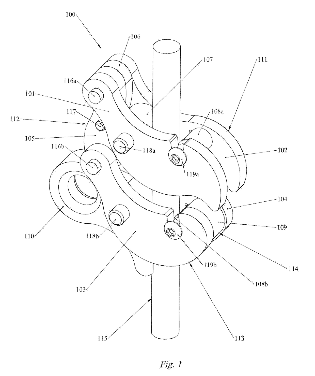
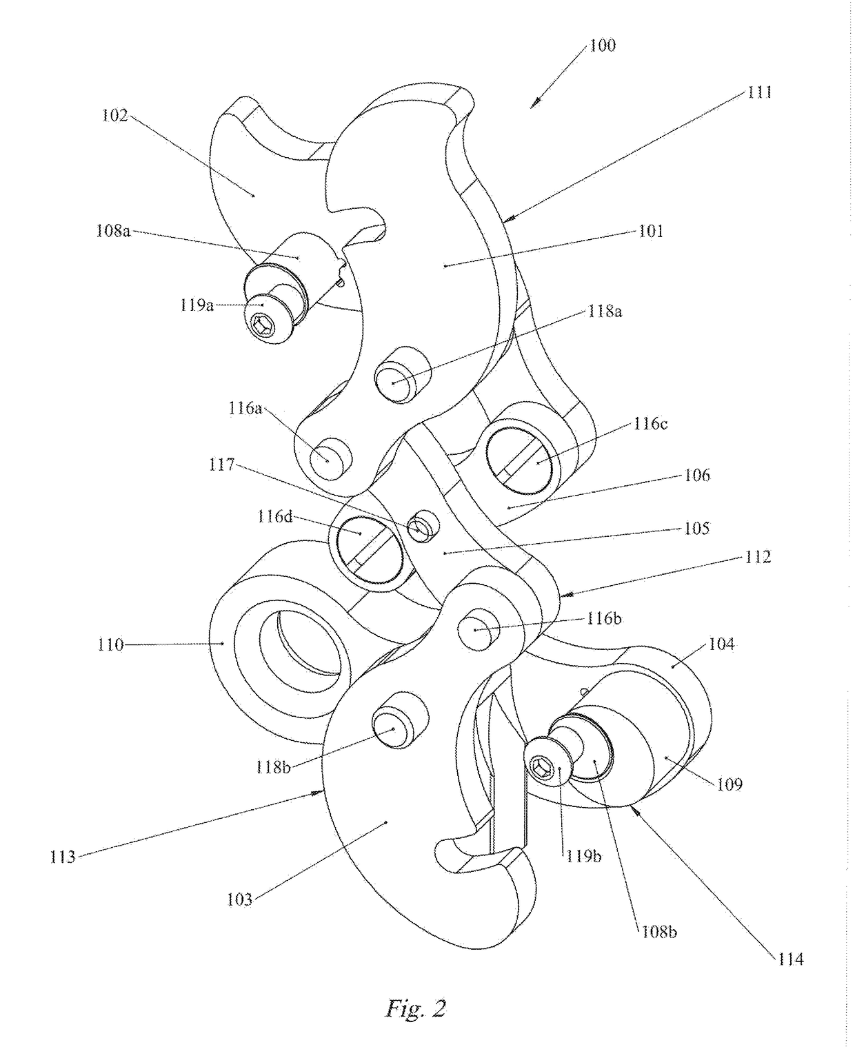
[0013]FIG. 1 illustrates an on-rope work positioning device 100 for ascending and descending on a rope, in neutral or collapsed position on a rope 115. Device 100 comprises an upper assembly 111, a spine assembly 112, a lower assembly 113, and a pin / bollard assembly 114.

[0014]Upper assembly 111 comprises two generally parallel side plates 101 and 102. These side plates are elongate in shape, generally flat in cross section, are constructed of a rigid material appropriate for high wear and stress applications and comprise each a first, second, and third aperture arranged sequentially along the length, patterned such that the apertures of side plate 101 and 102 match. Both side plates 101 and 102 comprise a pivot end and a control end. The distal aperture of the control end of side plate 101 is formed as a slot sized to mate an end portion of eccentric pin 108a, which is bolt 119a, and is formed such that bolt 119a may pass out of the slot by means of rotation of either side plate 101...


PUM


Abstract

A rope-climbing device has an upper assembly with planar side plates spaced apart by a roller, such that the side plates rotate relative to one another about a roller axis, a spine unit comprising planar links of common width each of half the plate spacing, the links pivoted at a central point, and a lower assembly comprising third and fourth side plates spaced apart by a clamp element such that the third and fourth side plates are enabled to rotate relative to one another about the clamp axis, and the clamp element is enabled to clamp a rope between the plates. The device may be opened by aligning pivot points, a rope inserted, and closed on the rope. Engaged on the rope, the device may be set to slide on the rope, or clamp to the rope by action of a user.

Description

BACKGROUND OF THE INVENTION[0001]1. Field of the Invention[0002]The present invention pertains to a rope ascending / descending apparatus. The use of such apparatus relates to, but is not limited to: rope access, rock climbing, rescue work, and more specifically to work positioning as pertains to rope-assisted tree work.[0003]2. Description of Related Art[0004]In many jobs and activities it is highly desirable to provide a safe, secure, and easy to use way to both climb and descend a rope. This includes tree work, rock climbing, rescue work, and tower or building repair or maintenance. The nature of tree work in particular also requires that such systems / devices / apparatus allow for movement of a climber both vertically and horizontally within a tree. Traditional systems rely on friction hitches or prusik knots applied to a doubled length of rope which runs over a limb or other anchor point in a dynamic 2:1 fashion. This is referred to as doubled dynamic rope technique (DdRT). More mod...

Claims


Application Information

Patent Timeline
Patent Type & Authority Patents(United States)
IPC IPC(8): A62B1/14A62B35/00
CPCA62B1/14A62B35/0081A62B1/06A63B29/024A63B29/08
Inventor MERRITT, JAIME A.
Owner MERRITT ARBOREAL DESIGN INC
Learn More