
Valve apparatus

a valve and valve technology, applied in the field of valve apparatus, can solve the problems of not being able to have both capabilities, affecting the performance of the seat so as to achieve the desired seat performance, prevent the sticking of the valve plug, and maintain the effect of seat performance in the valve closed sta

Active Publication Date: 2017-08-31
HONDA MOTOR CO LTD
View PDF5 Cites 1 Cited by
  • Summary
  • Abstract
  • Description
  • Claims
  • Application Information

AI Technical Summary

Benefits of technology

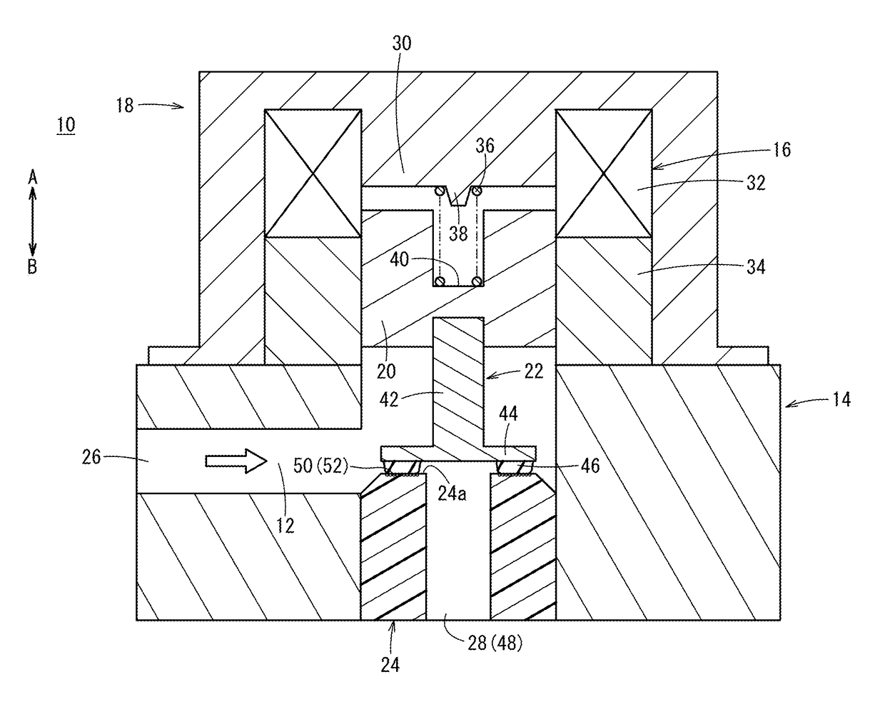
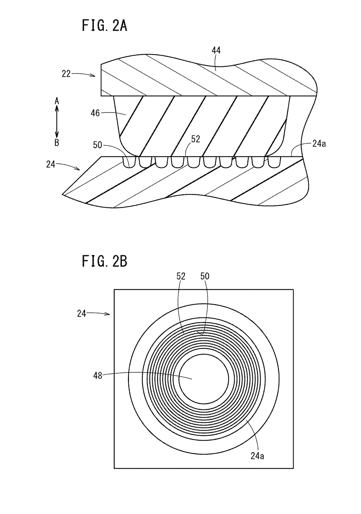
The present invention provides a valve apparatus wherein a plurality of annular grooves are formed on at least one of the valve plug and the valve seat surface facing each other. The annular grooves have different diameters that are concentric with each other. This design prevents sticking during valve opening operation while maintaining a desired seat performance when the valve plug is in the Valve closed state. The valve apparatus can prevent leakage of fluid through any scratch or groove formed between the recesses and the valve seat surface.

Problems solved by technology

However, in the above valve apparatus, since the plurality of recesses are provided to extend in the radial direction, respectively, for example, in the case where a small scratch or a groove is formed between any of the recesses and the valve seat surface due to molding failure at the time of producing the valve seat or due to contact between the valve seat and the valve plug, leakage of fluid occurs when the valve apparatus is in a valve closed state because the fluid flows in the radial direction through the scratch or the groove.
Consequently, by providing the recesses on the valve seat surface, though it is possible to prevent sticking of the valve plug in the valve opening operation, the seat performance in the valve closed state is degraded.
Therefore, it is not possible to have both of the capabilities, i.e., preventing sticking of the valve plug and maintaining a desired seat performance.

Method used


Image

  • Valve apparatus
  • Valve apparatus
  • Valve apparatus

Examples


Embodiment Construction

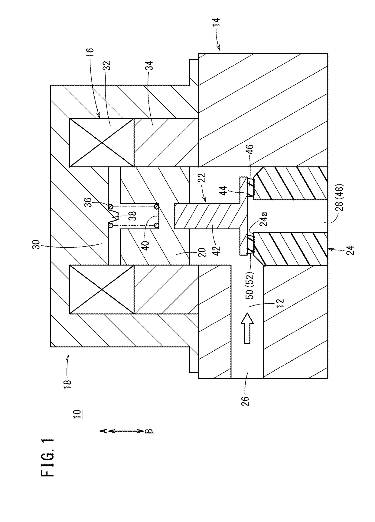
[0017]A valve apparatus 10 is used, for example, for switching the flow state of a fuel gas in a fuel cell system. As shown in FIG. 1, the valve apparatus 10 includes a body 14 having an internal flow channel 12 as a passage of fluid, a housing 18 provided on an upper portion of the body 14 and containing therein a solenoid part 16, a movable core 20 configured to move in an axial direction (indicated by arrows A and B) by excitation of the solenoid part 16, a valve plug 22 coupled to the movable core 20 and configured to switch a communication state of the flow channel 12, and a valve seat member 24 provided in the body 14 for allowing the valve plug 22 to be seated on the valve seat member 24.

[0018]Hereinafter, a side of the valve apparatus 10 where the housing 18 is provided will be referred to as a “proximal end side” (i.e., a side indicated by the arrow A), and another side of the valve apparatus 10 where the body 14 is provided will be referred to as a “distal end side” (a sid...


PUM


Abstract

In a valve apparatus, an annular contact portion made of elastic material is provided on a valve portion of a valve plug. A plurality of annular grooves are formed on a proximal end surface of a valve seat member which abuts against the contact portion. The annular grooves are formed around a communication hole through which fluid flows. The annular grooves have different diameters, and are concentric with one another.

Description

CROSS-REFERENCE TO RELATED APPLICATION[0001]This application is based upon and claims the benefit of priority from Japanese Patent Application No. 2016-035682 filed on Feb. 26, 2016, the contents of which are incorporated herein by reference.BACKGROUND OF THE INVENTION[0002]Field of the Invention[0003]The present invention relates to a valve apparatus having a valve plug movable in an axial direction, and which is configured to interrupt a communication state of a flow channel as a passage of fluid when the valve plug is seated on a valve seat surface of a body.[0004]Description of the Related Art[0005]Heretofore, valve apparatuses capable of switching a flow state of fluid flowing thorough a flow channel has been known. For example, in Japanese Laid-Open Patent Publication No. 2013-050145, a valve plug is provided inside a body so as to be movable in an axial direction, and the valve plug is coupled to a piston rod, while the valve plug can be seated on a valve seat provided inside...

Claims


Application Information

Patent Timeline
IPC IPC(8): F16K1/36F16K25/00F16K1/12
CPCF16K1/36F16K31/0675F16K25/005F16K1/12F16K1/42F16K31/0655
Inventor HAKODA, KOJIKOYAMA, TOMOYOSHIOTAKI, HIROTAKAHATAKEDA, TOMOHIKOINOUE, SATOSHI
Owner HONDA MOTOR CO LTD
Learn More