
Pencil sharpener

a pencil and sharpener technology, applied in the field of pencil sharpeners, can solve the problems of inability to efficiently perform shaving, inability to accurately adjust the feed roller, and worn core tip, so as to prevent unnecessary sharpening, prevent unnecessary sharpening, and improve the effect of sharpening

Active Publication Date: 2019-05-02
OSAKA CLIP CO LTD
View PDF3 Cites 1 Cited by
  • Summary
  • Abstract
  • Description
  • Claims
  • Application Information

AI Technical Summary

Benefits of technology

The present invention is a pencil sharpener that has several technical effects. Firstly, it ensures that the pencil is fully sharpened and prevents unnecessary sharpening. Secondly, the shaving stop means is not driven by the pressure of the core tip, but by a torque generation means, which prevents damage to the core tip. Thirdly, the pencil escapes from the shaving unit, improving the finished quality of sharpening and making the insertion force of the feed roller easier to set. Finally, the torque generation means can automatically perform operations from shaving to pencil ejection, improving workability and user experience.

Problems solved by technology

However, there is also a problem with color pencils and 2B and 3B pencils, which have soft cores, that when the core tip comes into contact with the stopper, the core tip is worn and accordingly, the gear that forces synchronization with the rotation of the feed roller is not disengaged, and the shaving continues; therefore, the shaving does not stop.
However, if the feeding force is reduced too much, a pencil may not be able to be fed in, or even if a pencil can be fed in, the shaving may not be able to be performed efficiently due to the small feeding force.
The adjustment of the feed roller is very difficult.

Method used


Image

  • Pencil sharpener
  • Pencil sharpener
  • Pencil sharpener

Examples


first embodiment

[0040]An embodiment of a pencil sharpener according to the present invention is described hereinafter, using the drawings. The following embodiment is an optimal example of the present invention, and the present invention is not especially limited to this example.

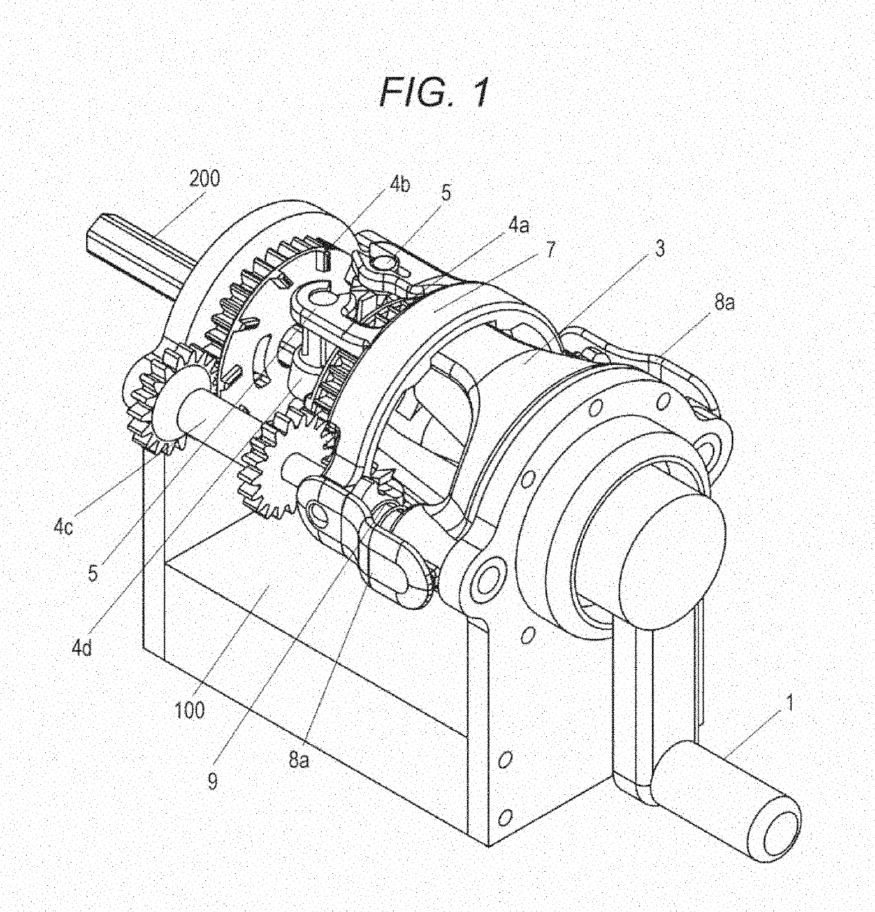
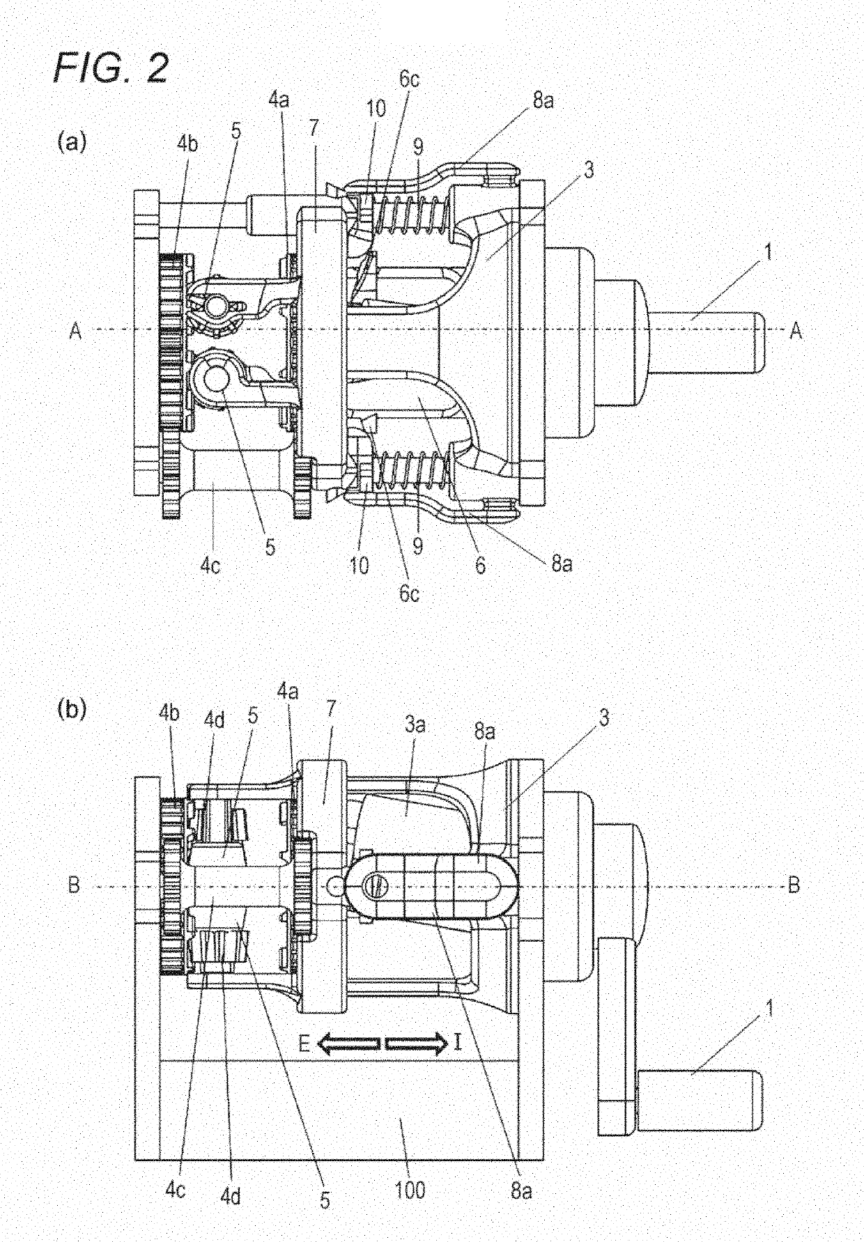
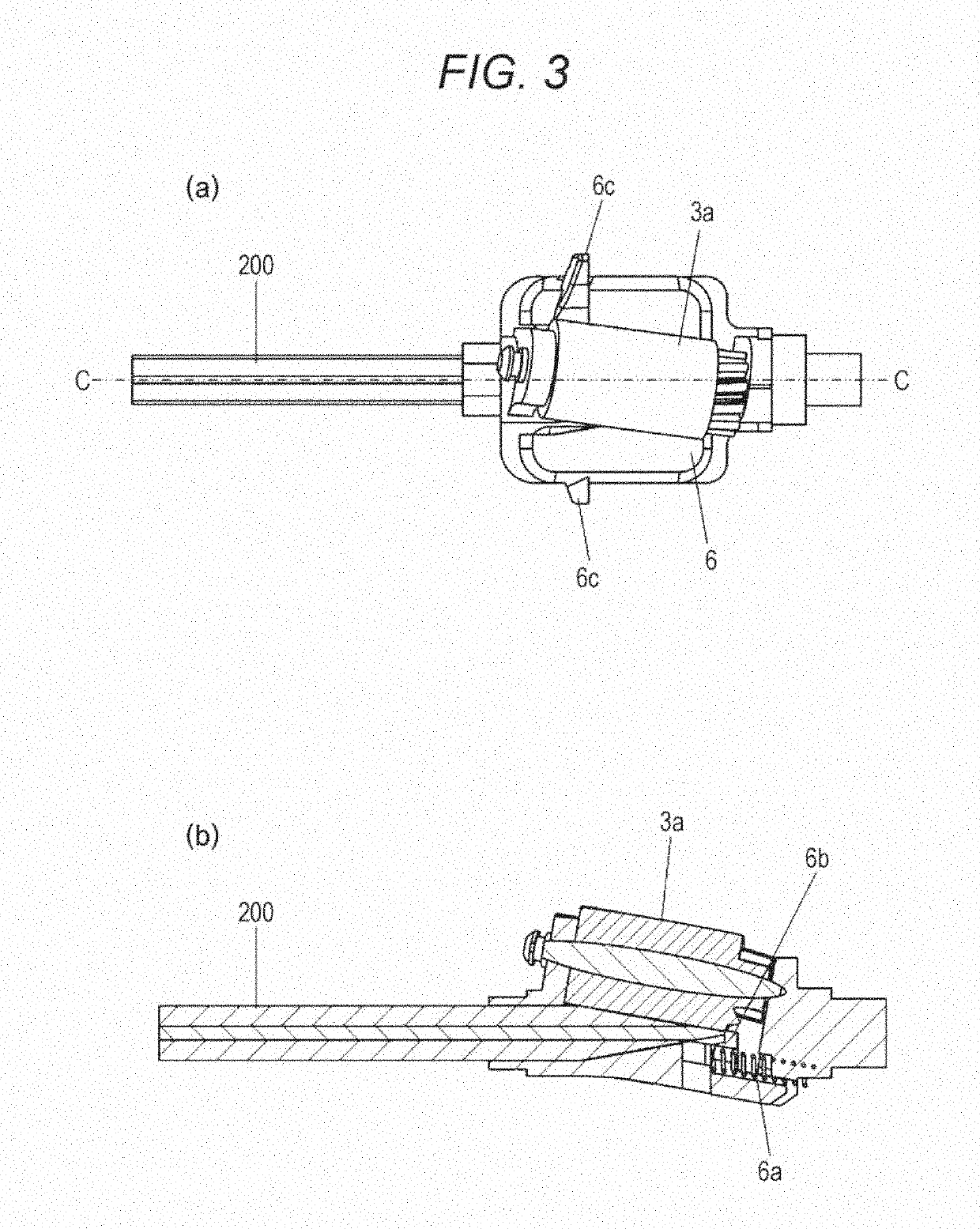
[0041]Firstly, a main configuration of the pencil sharpener is described, using FIGS. 1 to 3(b).

[0042]FIG. 1 is a general view of the inside of the pencil sharpener, and is a perspective view in a state where a casing has been removed.

[0043]FIGS. 2(a) and 2(b) are an internal top view and an internal side view of the pencil sharpener in a state where a pencil is not inserted.

[0044]Moreover, FIGS. 3(a) and 3(b) are part drawings of a cutter frame and a core tip detection unit of the pencil sharpener, and are a top view and a C-C cross-sectional view.

[0045]The pencil sharpener is a pencil sharpener including, in addition to the casing, a torque generation means 1 that generates rotational torque by manual rotation of a crank ...

second embodiment

[0109]In the first embodiment, the configuration has been described in which the pencil biasing means that converts the rotation of the cutter frame into the motion of biasing a pencil in the insertion direction and biases the pencil in the insertion direction is capable of translating in the pencil insertion direction and the pencil ejection direction. In other words, the configuration has been disclosed which stores energy that is generated by the pencil biasing means moving in the pencil insertion direction when the pencil is inserted, releases the energy in conjunction with the sharpening completion detection means, and accordingly translates the pencil biasing means in the pencil ejection direction to move the pencil in the pencil ejection direction.

[0110]On the other hand, in the second embodiment, a configuration is described in which the pencil biasing means does not translate in the pencil insertion direction and the pencil ejection direction. The pencil biasing means does ...


PUM


Abstract

The present invention provides a sharpening completion detection mechanism that does not apply a heavy load to a core tip, and especially proposes a mechanism that moves a pencil in an ejection direction immediately when the sharpening completion detection mechanism detects completion of sharpening to mitigate damage to the core. Specifically, a pencil sharpener according to the present invention includes: a slide unit that translates in pencil insertion and pencil ejection directions; a pencil biasing means supported by the slide unit; a slide locking means that locks a translation position of the slide unit upon the slide unit translating in the insertion direction; and a slide unit unlocking means that releases the lock for the translation position of the slide unit upon the sharpening completion detection means detecting a fully sharpened state of the pencil, and includes slide unit ejecting means that biases the slide unit in the ejection direction with energy stored by movement of the slide unit to a lock position.

Description

TECHNICAL FIELD[0001]The present invention relates to a pencil sharpener.BACKGROUND ART[0002]Recent years' pencil sharpeners are provided with a mechanism for preventing sharpening too much. In other words, a mechanism is provided which, for example, stops shaving when the core tip has been shaved to a desired thickness, and notifies a user of completion of the shaving.[0003]For example, in a pencil sharpener having a feed roller that rotates in conjunction with the rotation of a crank to feed a pencil into a cutter frame, a stopper is provided in a predetermined position of the cutter frame. The pencil sharpener is configured in such a manner that when the core tip comes into contact with the stopper, the feed roller moves in a direction away from the core tip due to a reaction force to the contact, and is disengaged from a gear that synchronizes the rotation of the crank with the rotation of the feed roller to stop the rotation of the feed roller.[0004]However, there is also a pro...

Claims


Application Information

Patent Timeline
Patent Type & Authority Applications(United States)
IPC IPC(8): B43L23/04B43L23/00B43L23/08
CPCB43L23/04B43L23/008B43L23/08
Inventor ITOI, KAZUO
Owner OSAKA CLIP CO LTD
Learn More