Engine air-intake control device and engine air-intake control method

a technology of air-intake control and control device, which is applied in the direction of electric control, machines/engines, instruments, etc., can solve the problems that the drive/stop of the driving switch element or the power supply relay is not always reliable, and achieve the effect of improving safety

Inactive Publication Date: 2005-01-18
MITSUBISHI ELECTRIC CORP
View PDF10 Cites 14 Cited by
  • Summary
  • Abstract
  • Description
  • Claims
  • Application Information

AI Technical Summary

Benefits of technology

[0011]A first object of the present invention is to provide an engine air-intake control device and an engine air-intake control method enabling to improve such problems as mentioned above, and to improve safety further by effectively utilizing a dual system constitution as well as rationalizing sharing of functions as a drive control circuit and a monitoring control circuit.
[0012]A second object of this invention is to provide an engine air-intake control device and an engine air-intake control method enabling to improve safety further by automatically conducting an operation confirmation of a safety control function at the start-up of operation.
[0020]As a result, an advantage is obtained such that it becomes possible to reliably stop the drive of the motor, which controls the opening of the intake valve of the engine at the time of occurrence of any abnormality thereby enabling to improve safety in the control.
[0023]As a result, another advantage is obtained such that it is possible to provide an engine air-intake control method enabling to reliably stop the drive of the motor at the time of occurrence of any abnormality, and to improve safety in the control.

Problems solved by technology

In this vehicle control device, e.g., in the case where a microprocessor contained in an on-vehicle electronic device such as electronic throttle control device runs away, this trouble is detected by means of a watchdog timer to start up the microprocessor again; further, the fact that an error operation has occurred is stored in a storage element to interrupt a load relay for switching a load power supply such as throttle valve open / close motor.
However, on the supposition that an improper soldering at an electronic substrate, getting mixed of a conductive foreign substance, breakdown of an electronic part or the like occur, any error takes place in a connection relation between the drive control circuit and the driving switch element and a connection relation between the monitoring control circuit and a power supply relay electromagnetic coil.
Consequently, a problem exits in that a dangerous state occurs in which the drive / stop of the driving switch element or power supply relay is not always performed reliably.

Method used


Image

  • Engine air-intake control device and engine air-intake control method
  • Engine air-intake control device and engine air-intake control method
  • Engine air-intake control device and engine air-intake control method

Examples


third embodiment

for explaining a drive control operation of the engine air-intake control device according to the

[0036]FIG. 12 is a flowchart for explaining a monitoring control operation of the engine air-intake control device according to the third embodiment.

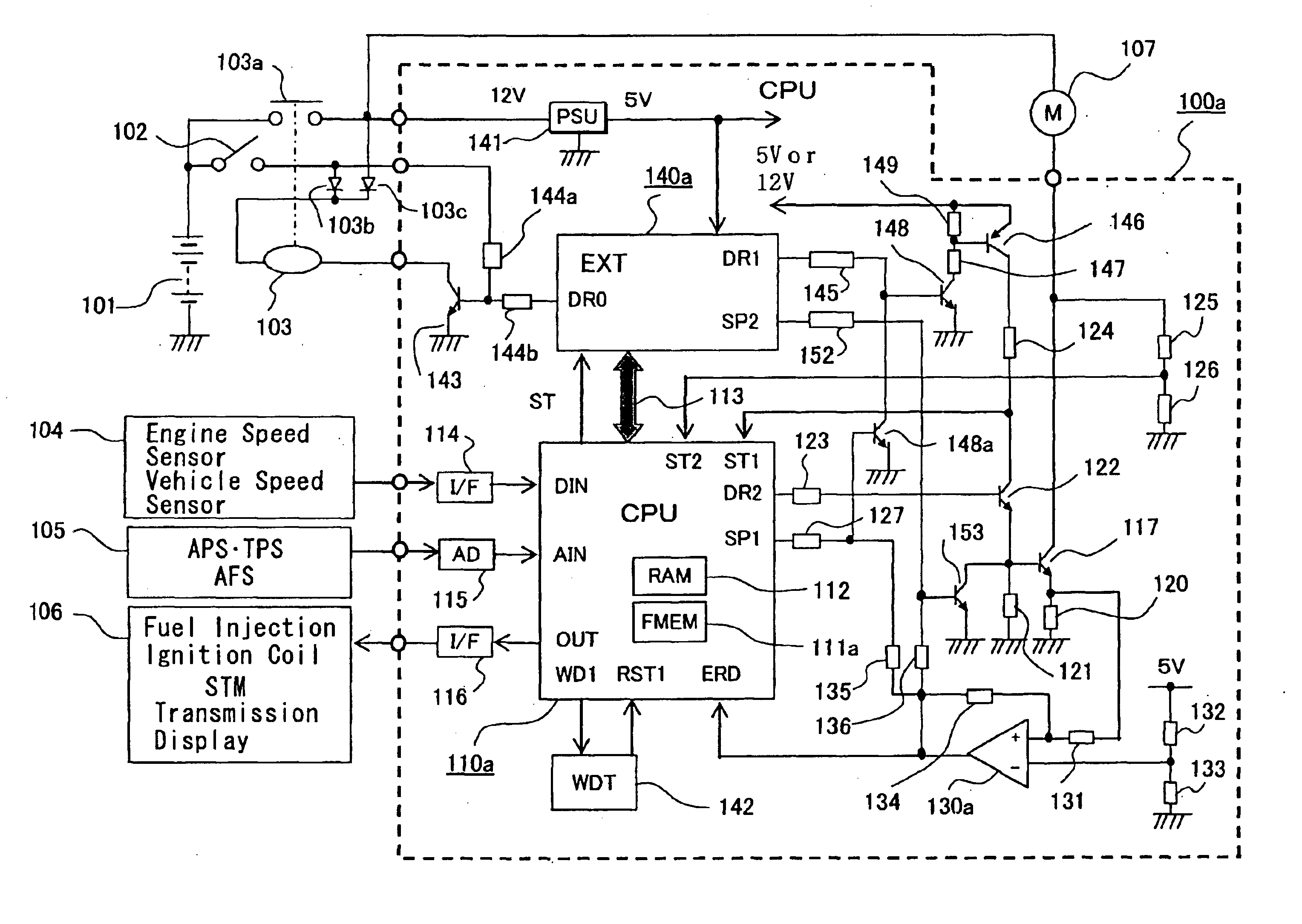
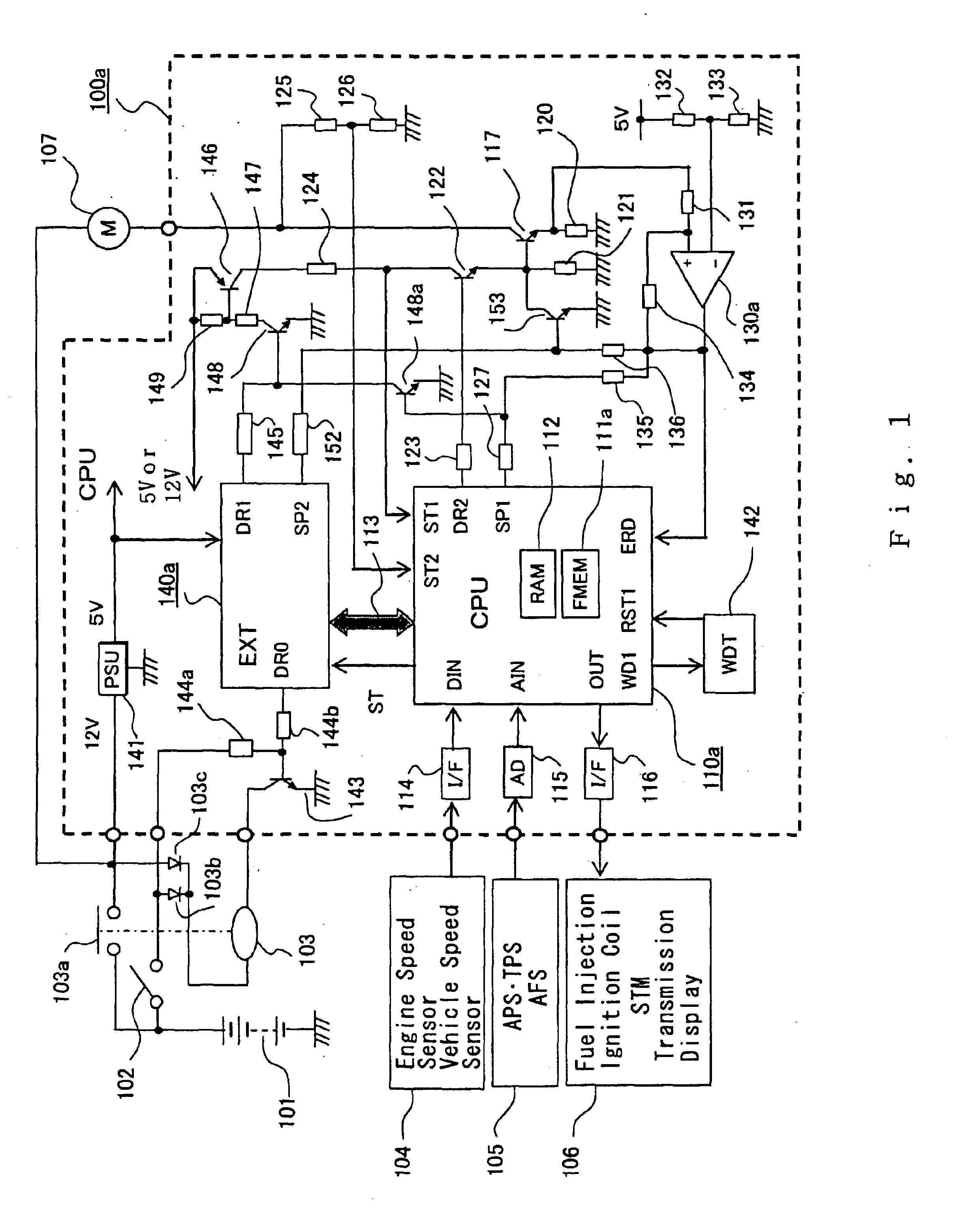
[0037]FIG. 13 is a block diagram showing constitution of an engine air-intake control device according to a fourth preferred embodiment.

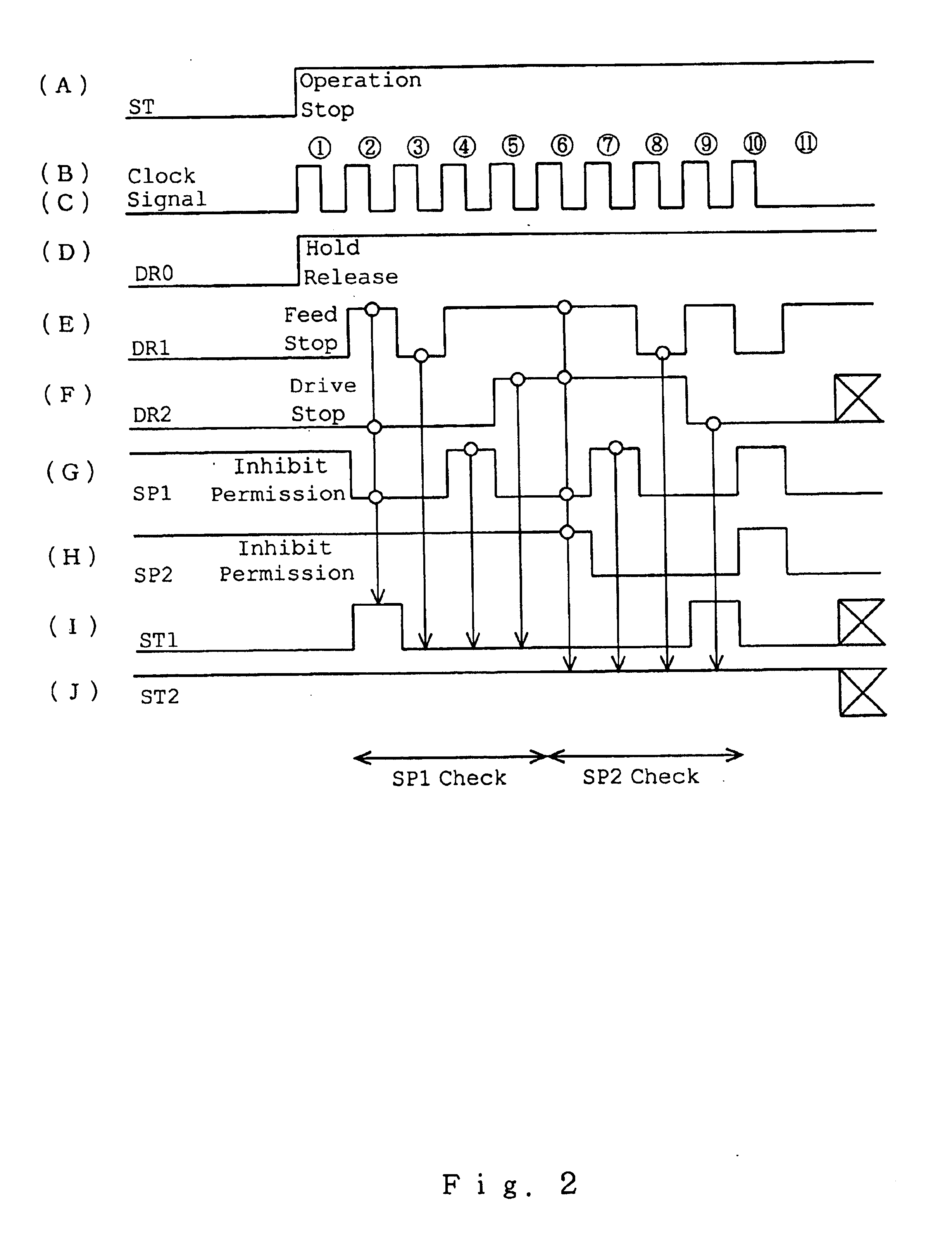
[0038]FIG. 14 is a time chart for explaining a startup sequence of the engine air-intake control device according to the fourth embodiment.

[0039]FIG. 15 is a flowchart for explaining a drive control operation of the engine air-intake control device according to the fourth embodiment.

[0040]FIG. 16 is a flowchart for explaining a monitoring control operation of the engine air-intake control device according to the fourth embodiment.

DESCRIPTION OF THE PREFERRED EMBODIMENTS

[0041]Hereinafter, with reference to the drawings, several preferred embodiments of the present invention are described.

[0042]In addition, be...


PUM


Abstract

A drive control circuit generates a conduction drive output responsive to a detection output of an accelerator pedal depression degree sensor and an air-intake throttle-valve opening sensor, and controls a driving switch element connected to an air-intake throttle-valve opening control motor. A monitoring control circuit drives a control circuit power supply interruption element that closes a control power supply circuit of the driving switch element, and stops control operation of the driving switch element by a conduction-inhibit output. The drive control circuit can stop operation of a power supply interruption element by a feed-inhibit output. At the time of starting operation, a status signal determines activeness of the feed-inhibit output and conduction-inhibit output, after confirming that those outputs are normal, the inhibition is released. Thus, an engine air-take control device capable of reliably stopping the motor upon occurrence of any abnormality thereby improving safety in control is provided.

Description

BACKGROUND OF THE INVENTION[0002]1. Field of the Invention[0003]The present invention relates to a drive control device of an intake valve open / close motor for controlling an air-intake of an engine. More specifically, the invention relates to improvement of an engine air-intake control device arranged such that a monitoring control circuit is added to a drive control circuit of the above-mentioned motor and a power feed with respect to the above-mentioned motor is interrupted at the time of occurrence of any abnormality.[0004]2. Description of the Related Art[0005]An air-intake control device that controls by means of an electromotive motor an air-intake throttle-valve opening of an engine in accordance with a depression degree of an accelerator pedal has been popularly employed in practical use. To improve safety in this type of electronic throttle control, however, a monitoring control circuit is usually added with respect to a drive control circuit of an electromotive motor, and...

Claims


Application Information

Patent Timeline
Patent Type & Authority Patents(United States)
IPC IPC(8): F02D11/10F02D9/02F02D41/20F02D41/22F02D45/00
CPCF02D11/107Y02T10/42Y02T10/40
Inventor HASHIMOTO, KOHJINAKAMOTO, KATSUYA
Owner MITSUBISHI ELECTRIC CORP
Why Eureka
Try Eureka