Parabolic golf club system

a golf club and system technology, applied in the field of parabolic golf club systems, can solve the problems of golfers simply not being able to customize golf clubs in the early days, unable to achieve “pushed” or “pulled” shots, etc., and achieve broad performance characteristics without sacrificing stability and forgiveness

Inactive Publication Date: 2017-03-28
NCD ENGINEERED PROD INC
View PDF47 Cites 27 Cited by
  • Summary
  • Abstract
  • Description
  • Claims
  • Application Information

AI Technical Summary

Benefits of technology

[0018]In one embodiment the planar striking face, located at the directrix, may be integrally formed with the putter head. The planar striking face may be smooth or include various patterns such as overlapping arcuate or horizontal grooves or furrows. Additionally, the planar striking face may contain an insert cavity where a face insert may be installed. The face insert allows a golfer to select from a wide array of materials, patterns and the like to customize the impact properties of the planar striking face to suit their putting technique and individuality.
[0019]In one embodiment the shaft is mounted into a simple angled bore located at the focus in the club head. The shaft angle and location are fixed and are not easily adjustable by the golfer. Additionally, the shaft mounting device may utilize an interchangeable hosel to join the shaft to the club head. The interchangeable hosel allows the golfer to select from various hosel configurations to customize shaft position, shaft feel, and aesthetic properties. The interchangeable hosel also allows a golfer to easily change between a right-hand club and a left-hand golf club orientation.
[0021]Additionally, the weights may be substantially parabolic in shape and consist of a single parabolic weight, several thin parabolic weight plates, or a parabolic weight cartridge. These parabolic weight styles may utilize a variety of materials allowing golfers to significantly vary club head mass, MOI, and CG. The single parabolic weight provides a consistent weight throughout the parabolic volume and may serve to concentrate the weight near the arcuate parabolic path.
[0022]The parabolic weight plates may serve to provide weight “layering” from the top region to the sole region. The parabolic weight plates allow the golfer to concentrate weight near the top region, sole region, or somewhere in between based on material composition and density of each parabolic weight plate.
[0023]The parabolic weight cartridge may receive many smaller weights held within pockets bored into the weight cartridge. The entire assembly is installed in a mating parabolic slot located in the club head and the weight cartridge is secured to the club head with fasteners. The parabolic weight cartridge allows weight adjustment in all planes from heel region, toe region, top region, sole region or anywhere in between based on weight density and placement locations within the parabolic weight cartridge.
[0024]The combination of parabolic club head geometry, with the face located at the directrix and shaft located at the focus allows golfers to create a very light club head without sacrificing stability and forgiveness. A lighter club head moves the CG closer to the butt end of the grip creating a simulated “anchored” putting stroke feel. Additionally, the combination of the parabolic head, weight adjustment opportunities, hosel and face customization options allow golfers to attain a golf club truly customized by them with broad performance characteristics suiting all styles and levels of play.

Problems solved by technology

The ability to customize a golf club in the early days was simply not available to golfers.
This increased twisting is increasingly likely to result in a “pushed” or “pulled” shot.
However, unless the shaft is placed in an optimal location for the geometry, the club head can still twist on off-center hits likely resulting in a “pushed” or “pulled” shot.
The shaft angle and location are fixed and are not easily adjustable by the golfer.

Method used


Image

  • Parabolic golf club system
  • Parabolic golf club system
  • Parabolic golf club system

Examples


operation — embodiment 2

Operation—Embodiment 2—FIG. 9A

[0158]An exploded view of an alternative embodiment detailing a club head assembly 39 is illustrated in FIG. 9A. Club head assembly 39 is used to describe the operation. The manner of using golf club 40′ (FIGS. 4A and 4B) to strike a golf ball is similar to the method discussed previously. The golfer rests sole region 91 on the ground in their setup position. The golfer grasps grip 54 utilizing their regular golf club or putting grip, depending on club head 50 type, and aligns the front sight aid 68′ with the golf ball and the rear sight aid 70′ along the intended travel path of the golf ball. However, there are several alternative features allowing golfers to customize club head assembly 39 to their individual style.

Hosel Configuration and Operation

[0159]The golfer first configures golf club 40′ for a right hand (FIG. 4A) or left hand (FIG. 4B) golfer. The golfer changes from a right hand (FIG. 4A) configuration to a left hand (FIG. 4B) configuration b...

embodiments — 10a through 10c

Alternative Embodiments—10A Through 10C

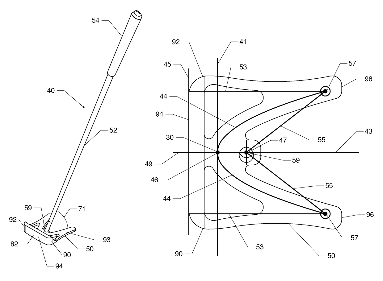
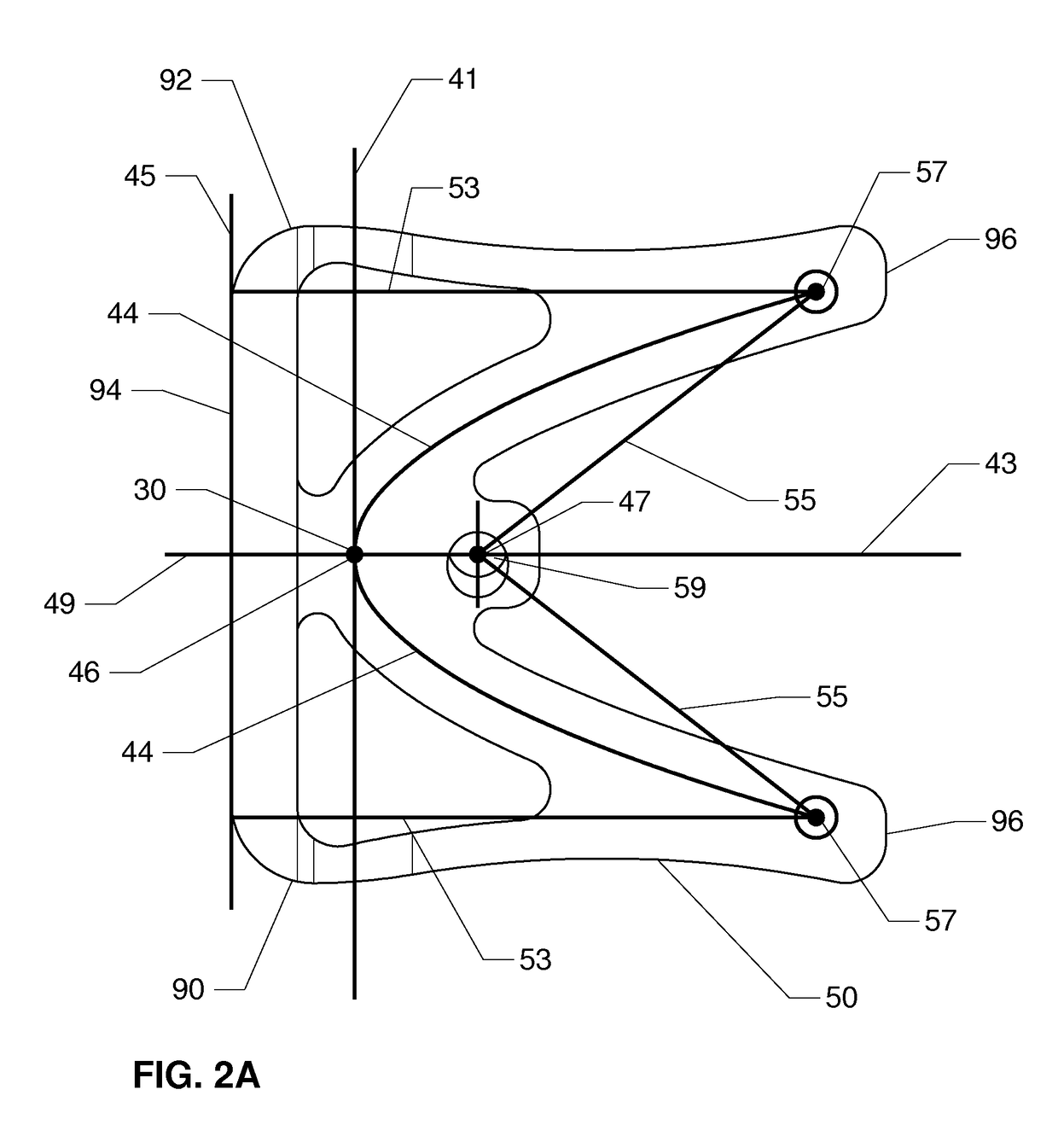
[0179]One alternative embodiment of a golf club assembly 100 consists of an alternative club head 101 shape illustrated in FIGS. 10A through 10C (perspective views and side view). In one alternative embodiment golf club assembly 100 consists of a club head 101 in a substantially block shaped configuration. Golf club assembly 100 consists of the components described earlier such as grip 54, shaft 52, face region 94 located at directrix 45 (FIG. 2A), and shaft 52 attached to club head 101 by a hosel 59 (FIG. 3D) or a interchangeable hosel 58 (FIGS. 8A through 8F) located at focus 47.

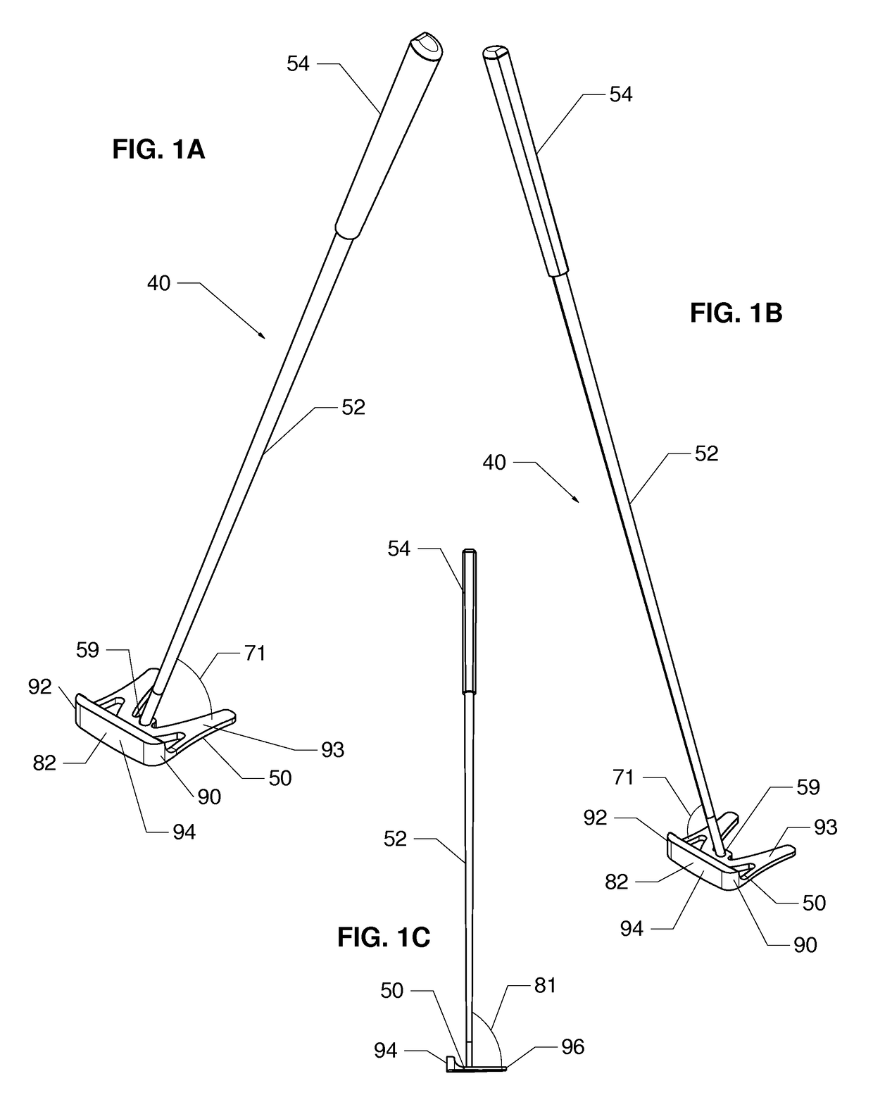
[0180]Golf club assembly 100 is illustrated in a right-hand configuration in FIG. 10A and a left-hand configuration is illustrated in FIG. 10B. Shaft 52 may form a lie angle 71 between a horizontal plane defined by top region 93. Lie angle 71 is measured substantially parallel to face region 94 with shaft 52 angled toward heel region 90 or toe region 92 at various ang...

embodiments — 12c and 12d

Alternative Embodiments—12C and 12D

[0194]A perspective view and bottom view of an alternative embodiment of a club head 101″ are illustrated in FIGS. 12C and 12D respectively. In one alternative embodiment, club head 101″ consists of a singular parabolic weight receiving bore 118 concealed in sole region 91 in place of the plurality of weight pockets 102 (FIGS. 12A and 12B). In the alternate embodiment club head 101″ consists of similar features and construction methods and materials previously described.

[0195]Parabolic weight receiving bore 118 may be approximately between 0.100 and 1.000 inches in depth and shallower than the overall club head 101″ depth creating a blind cavity. Additionally, parabolic weight receiving bore 118 must be deep enough for alternative parabolic weight 116 (FIGS. 14A through 14D) and parabolic weight cartridge 121 (FIGS. 15A through 15E) to be flush or slightly recessed into sole region 91. The depth prevents alternative parabolic weight 116 (FIGS. 14A ...


PUM


Abstract

A parabolic golf club system having a club head consisting of a parabolic path with a club face positioned coincident with the directrix and hosel (shaft) positioned at the focus. In other embodiments bores may be added along the parabolic path where various weights are installed to alter the club head properties such as MOI, CG, and overall mass. In other embodiments a substantially parabolic shaped bore may be formed in the club head allowing installation of parabolically shaped weights, weight plates, weight cartridges and the like to further alter club head properties. Further customization is achieved by allowing a golfer to select from various face inserts, face patterns, hosel configurations, and sight aid choices.

Description

BACKGROUNDPrior Art[0001]The following is a tabulation of some prior art that appears relevant:[0002]U.S. patentsPat. No.Kind CodeIssue DatePatentee4,340,230N / A1982 Jul. 20Churchward4,895,371N / A1990 Jan. 23Bushner5,335,913N / A1994 Aug. 9White5,688,189N / A1997 Nov. 18Bland6,749,523B12004 Jun. 15Forzano7,156,752B12007 Jan. 2Bennett7,331,876B22008 Feb. 19Klein7,404,772B22008 Jul. 29Niigata TLO Corp.8,096,039B22012 Jan. 17Cobra Golf Inc.8,382,604B22013 Feb. 26Dogleg Right Corp.[0003]U.S. Patent Application PublicationsPatent NumberKind CodePubl. DateApplicant2008 / 0261715A12008 Oct. 23Carter2010 / 0190573A12010 Jul. 29Boyd2011 / 0275453A12011 Nov. 10Nike, Inc.2012 / 0088641A12012 Apr. 12Shah2013 / 0203522A12013 Aug. 8Nike, Inc.Nonpatent Literature Documents[0004]Sauerhaft, Rob; et. al., Golf Magazine, “23 New Drivers Tested & Rated” (March 2014)[0005]Sauerhaft, Rob; et. al., Golf Magazine, “Club Test 2013: Putters” (June 2013)[0006]Dee, Mark, Golf Magazine, “New Putters: Mallet Mania” (September 2...

Claims


Application Information

Patent Timeline
Patent Type & Authority Patents(United States)
IPC IPC(8): A63B53/02A63B53/00A63B53/04
CPCA63B53/02A63B53/007A63B53/0487A63B53/023A63B60/02A63B2053/0491
Inventor DUNNELL, NATHANIELDUNNELL, JOSHUA
Owner NCD ENGINEERED PROD INC
Why Eureka
Try Eureka