Nail removal tool

a technology for nail removal and nail clipping, which is applied in the field of nail clipping tools, can solve the problems of affecting the installation and function of new shingles, tearing through the new shingles, and the most difficult time-consuming tasks of removing the nails used to secure the old shingles, and achieves the effect of being effective and yet inexpensiv

Inactive Publication Date: 2017-03-28
RALPH GREGORY W
View PDF13 Cites 3 Cited by
  • Summary
  • Abstract
  • Description
  • Claims
  • Application Information

AI Technical Summary

Benefits of technology

[0002]When re-roofing, one of the most difficult, time-consuming tasks is removing the nails used to secure the old shingles. If these nails are not removed, they can tear through the new shingles and interfere with their proper ins...

Problems solved by technology

When re-roofing, one of the most difficult, time-consuming tasks is removing the nails used to secure the old shingles.
If these nails are not removed, they can tear t...

Method used


Image

  • Nail removal tool
  • Nail removal tool
  • Nail removal tool

Examples


Embodiment Construction

)

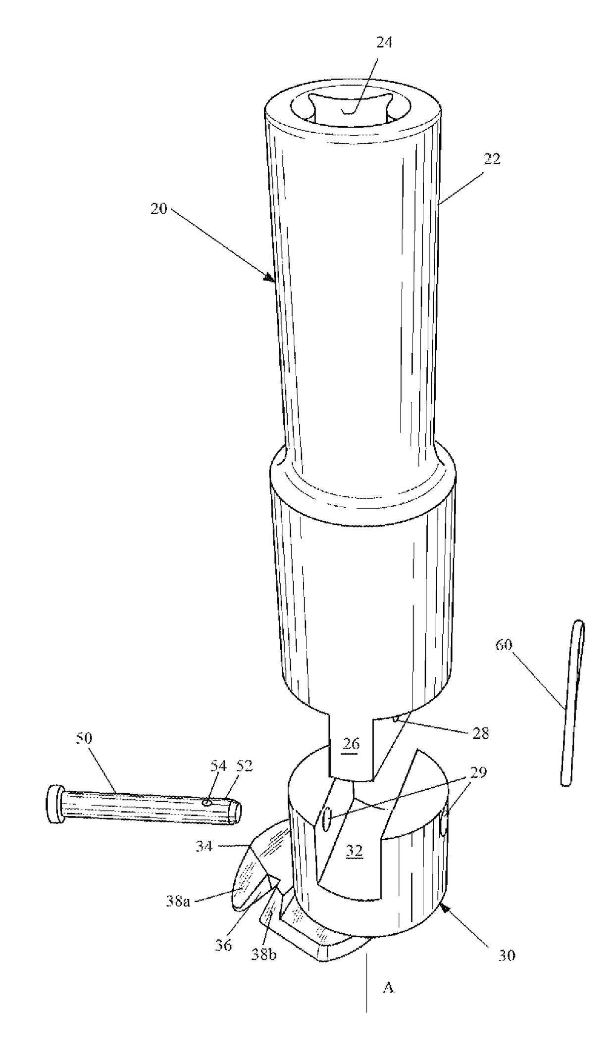
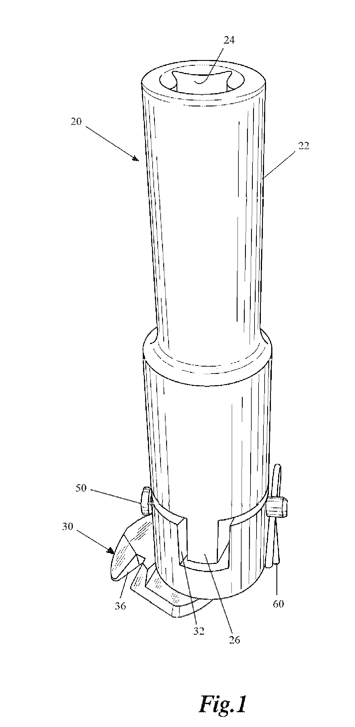
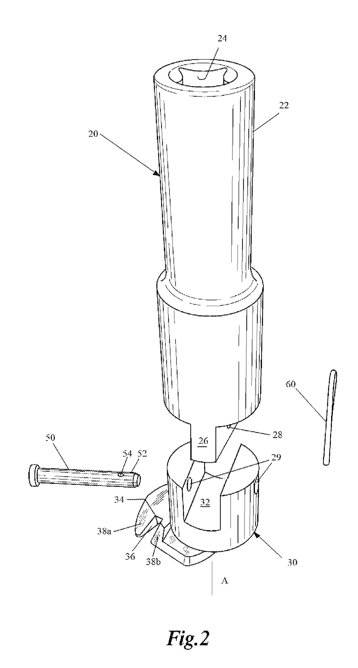
[0010]A first embodiment of the nail removal tool of the present invention is depicted in FIGS. 1 and 2 generally at 20. As best seen in FIG. 2, nail removal tool 20 comprises an adapter for a rotary power tool such as a rotary pneumatic impact driver and includes a drive shaft 22 engagable with a chuck of the rotary power tool (not shown). Drive shaft 22 has an internal recess 24 depicted here as being square, since that is the normal configuration of the male protrusion which it engages. It will be understood that other shapes are within the scope of the present invention. Drive shaft 22 has a diametrically extending drive blade 26 depicted as a conventional straight blade, although here, again, other shapes are within the scope of this invention.

[0011]Cylindrical bit 30 has a diametrically extending recess 32 which receives drive blade 26 drive shaft 22. Cylindrical bit 30 has an upper cylindrical portion 33 with a lower foot 34. Foot 34 has a slot 36 for receiving a body portio...


PUM


Abstract

A nail removal tool in the form of an adapter for attachment to the drive socket of a rotary driver such as a rotary pneumatic impact driver. The adapter includes a drive shaft engagable with the chuck of the pneumatic driver, a cylindrical bit with a slot for receiving the body of a nail and a ramp for engaging under the head and lifting it to dislodge the nail from its embedded location. Slop between the drive blade and the slot in the cylindrical bit serves as a flexible connection to provide proper presentation of cylindrical bit allowing wedging of the adapter beneath the head of a nail which is reluctant to be removed.

Description

BACKGROUND AND SUMMARY OF THE INVENTION[0001]The present invention is directed to the construction industry. More particularly, the present invention is directed to a nail removal tool in the form of an adapter securable to a rotary power tool, such as a rotary pneumatic impact drive motor.[0002]When re-roofing, one of the most difficult, time-consuming tasks is removing the nails used to secure the old shingles. If these nails are not removed, they can tear through the new shingles and interfere with their proper installation and functionality. In addition, they pose a safety hazard to the installers as they move about the roof. It is among the objects of the present invention to provide an effective, yet inexpensive, adapter to remove the old nails.[0003]In Applicant's earlier disclosure, issued as U.S. Pat. No. 8,341,818 issued Jan. 1, 2013, a coil spring was utilized to accommodate the force applied by the tool so as not to rip the head off the nail nor damage the drive. It was ...

Claims


Application Information

Patent Timeline
IPC IPC(8): B25C11/00B25F3/00
CPCB25C11/00B25F3/00
Inventor RALPH, GREGORY W.
Owner RALPH GREGORY W
Why Eureka
Try Eureka