Analyzing a skin condition from a video

a skin condition and video technology, applied in the field of video analysis, can solve the problems of difficult to properly assess expression, impossible to analyze a skin condition, wrinkles or twists, etc., and achieve the effect of properly analysing a skin condition

Active Publication Date: 2017-03-28
SHISEIDO CO LTD
View PDF15 Cites 2 Cited by
  • Summary
  • Abstract
  • Description
  • Claims
  • Application Information

AI Technical Summary

Benefits of technology

[0011]According to an embodiment of the present invention, it is possible to properly analyze a skin condition from expression wrinkles of a subject or a twist of the skin at the time of care.

Problems solved by technology

The conventional techniques such as those described above, however, perform assessment and the like of so-called fixed wrinkles, and there have been no techniques or the like of analyzing or assessing expression wrinkles, which are believed to be the cause of fixed wrinkles.
Therefore, it is difficult to properly assess expression wrinkles or a twist from an image, so that it has been impossible to properly determine expression wrinkles or a twist or to analyze a skin condition from potential wrinkles or the like caused by a change in the expression or daily care.

Method used


Image

  • Analyzing a skin condition from a video
  • Analyzing a skin condition from a video
  • Analyzing a skin condition from a video

Examples


example 1

[Strain Calculation Example 1]

[0090]According to Strain Calculation Example 1, with respect to displacements u and v, plane strain is given by Eq. (1) shown below:

εx=−∂u / ∂x,εy=−∂v / ∂y,γxy=−(∂u / ∂y+∂v / ∂x)(compression is positive)  (1)

where x and y indicate plane coordinates.

[0091]At this point, principal strain may be calculated by Eqs. (2) through (4) shown below:

[0092]ɛ1=ɛx+ɛy2+(ɛx-ɛy2)2+(γxy)2(2)ɛ2=ɛx-ɛy2+(ɛx-ɛy2)2+(γxy)2(3)γmax=ɛ1-ɛ2(4)

example 2

[Strain Calculation Example 2]

[0093]According to Strain Calculation Example 2, the area of a quadrangle that is an example of the analysis region is determined using a cross product, and a strain value is calculated from the ratio of areas before and after a change in the expression. Here, FIG. 6 is a diagram for illustrating Strain Calculation Example 2.

[0094]In the case of FIG. 6, when the analysis region is a quadrangle, letting the x and y coordinates of the vertices of the quadrangle be (0, 0), (a, b), (c, d) and (e, f), the area of the quadrangle is given by “Area=½×((√(a×d−b×c)2)+(√(c×f−d×e)2).”

[0095]Based on the above-described calculation, the strain value may be calculated as “Strain value=(the quadrangular area of a frame at the time of the deformation of the expression that is determined as a target) / (the initial quadrangular area of the frame (of a straight face).”

example 3

[Strain Calculation Example 3]

[0096]According to Strain Calculation Example 3, the strain of a centroid P (εx, εy) is calculated. FIG. 7 is a diagram for illustrating Strain Calculation Example 3.

[0097]Here, letting the initial coordinates of the vertices of a quadrangle are be (x1, y1), (x2, y2), (x3, y3) and (x4, y4) and letting the displacements of Nodes 1 through 4 be (u1, v1), (u2, v2), (u3, v3) and (u4, v4) as illustrated in FIG. 7, the strain of the centroid P may be calculated by Eqs. (5) and (6) shown below:

[0098]ɛx=ln⁢{1+(y2-y4)⁢u1+(y3-y1)⁢u2+(y4-y2)⁢u3+(y1-y3)⁢u4(x1-x3)⁢(y2-y4)-(y2-y4)⁢(y1-y3)}(5)ɛy=ln⁢{1+(x4-x2)⁢v1+(x1-x3)⁢v2+(x2-x4)⁢v3+(x3-x1)⁢v4(x1-x3)⁢(y2-y4)-(y2-y4)⁢(y1-y3)}(6)


PUM


Abstract

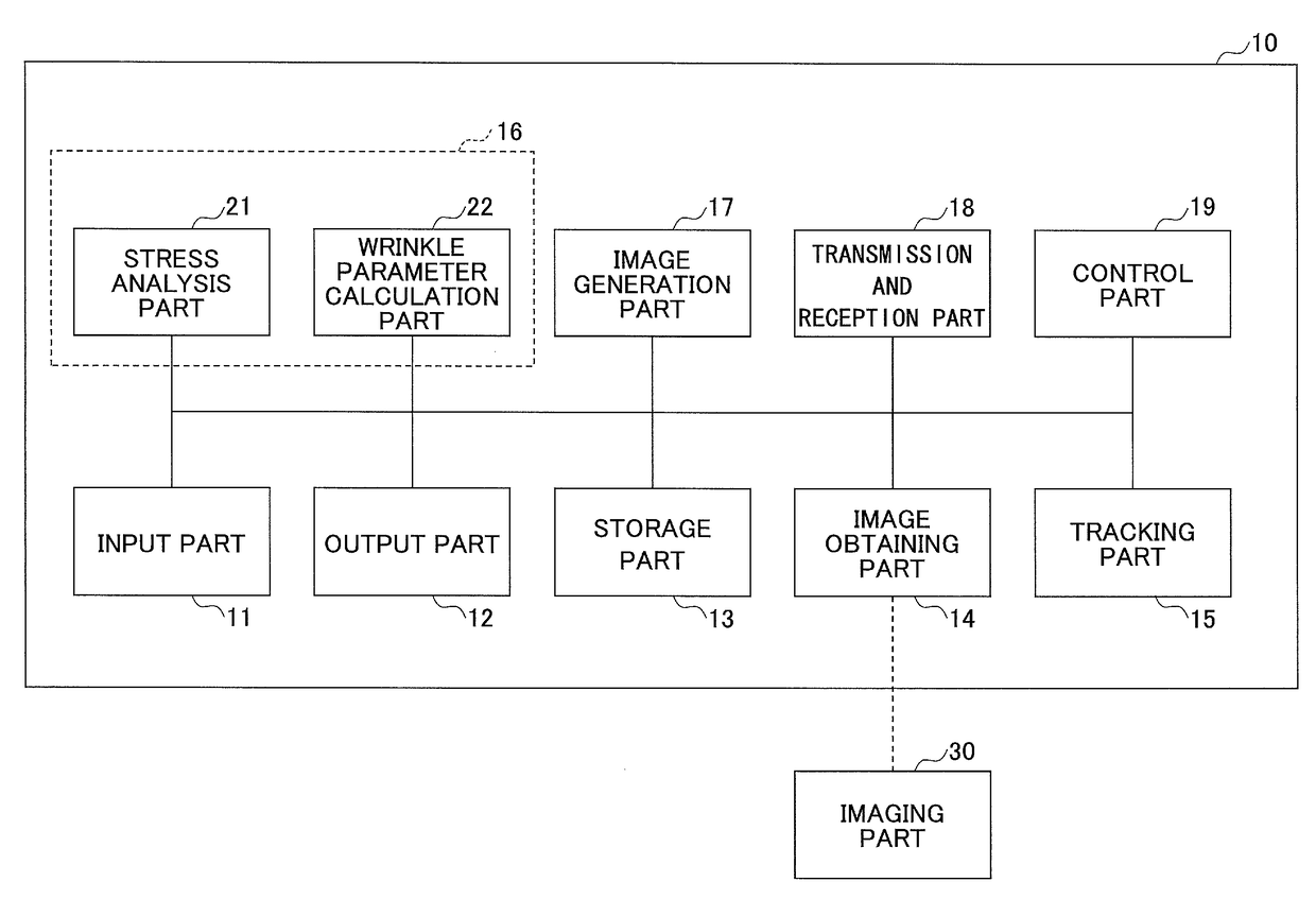
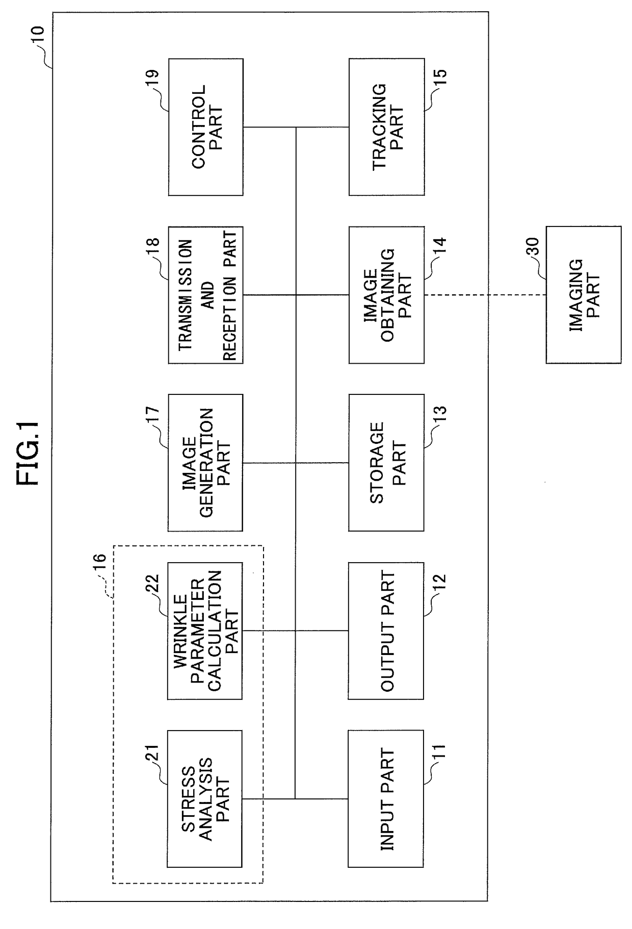
An image analysis apparatus that analyzes a skin condition from a video of the face of a subject captured with an imaging part includes a tracking part configured to track the amount of changes of multiple tracking points arranged in advance in an analysis region of the face based on a change in the expression of the face included in the video, and obtain the compression ratio of the skin in the analysis region based on the amount of changes, and a skin condition analysis part configured to analyze the skin condition of the subject based on the compression ratio obtained by the tracking part.

Description

TECHNICAL FIELD[0001]An embodiment of the present invention relates to image analysis apparatuses, image analysis methods, and image analysis programs, and in particular, relates to an image analysis apparatus, an image analysis method, and an image analysis program for properly analyzing a skin condition from expression wrinkles of a subject.BACKGROUND ART[0002]It has been the case that wrinkles formed on the face (such as the outer corners of the eyes and the cheeks) of a subject are caused with a twist due to a change in the facial expression (for example, laugh lines or anger lines) or pressing on the skin. Furthermore, for reasons such as aging or the decline of skin texture or elasticity, wrinkles no longer disappear even when the expression returns (so-called residual wrinkles), so as to ultimately become wrinkles that are caused irrespective of expressions (so-called fixed wrinkles). Accordingly, wrinkles have become a major cosmetic issue as a symbol of the aging phenomena ...

Claims


Application Information

Patent Timeline
Patent Type & Authority Patents(United States)
IPC IPC(8): G06K9/00G06T7/246A61B5/107G06T7/20G06K9/46A61B5/00A61B5/11
CPCG06K9/00268A61B5/0077A61B5/1079A61B5/1128A61B5/442G06K9/46G06T7/20G06T7/248A61B34/10G06K9/00315A61B5/7271G06K2009/4666G06T2207/30088A61B90/361G06V40/176G06V40/168
Inventor HARA, YUSUKEIWAI, ICHIROOHNISHI, HIROYUKI
Owner SHISEIDO CO LTD
Why Eureka
Try Eureka