
Fluid filtration system

a filtration system and fluid technology, applied in the direction of filtration separation, separation process, transportation and packaging, etc., can solve the problems of affecting the compactness of the sand layer, losing the ability to effectively filter water, etc., to achieve the effect of saving money, simple and fast, and little time away from producing filtered fluid

Inactive Publication Date: 2017-04-04
MANAUGH THOMAS SCOTT +1
View PDF6 Cites 0 Cited by
  • Summary
  • Abstract
  • Description
  • Claims
  • Application Information

AI Technical Summary

Benefits of technology

[0014]FWFC is efficient. Not using a conventional back wash procedure for cleaning a filter is advantageous because FWFC can be performed simply, quickly and completely, thus taking little time away from producing filtered fluid.
[0015]FWFC is economical. FWFC can save money when it is used to replace a system that demands frequent replacement of a filtering medium.

Problems solved by technology

The release of filtered particles could also result from other kinds of disruption to the compactness of the layer of sand, including (a) putting air bubbles in the water flowing upward through the sand, (b) moving the sand by mechanical stirring or vibration, and (c) shifting the sand about under the influence of a changing magnetic field in the case where the sand were a kind that could be attracted by a magnet.
After some period of filtering action in a constantly flowing stream of water, the sand can become clogged with small solid particles (here called “particulates”), thus losing its ability to filter water effectively.

Method used


Image

  • Fluid filtration system
  • Fluid filtration system
  • Fluid filtration system

Examples


Embodiment Construction

[0021]Forward Wash Filter Cleaning (FWFC) is a system and apparatus for allowing easy and inexpensive cleaning of a filtering medium. FWFC can be used in numerous applications wherein a filtering medium is used to remove particulates from a fluid and the filtering medium later needs to be cleaned.

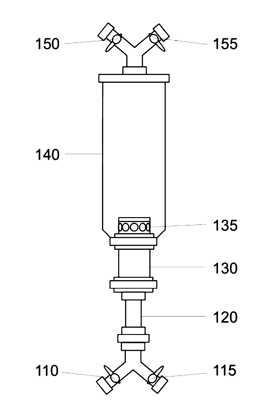
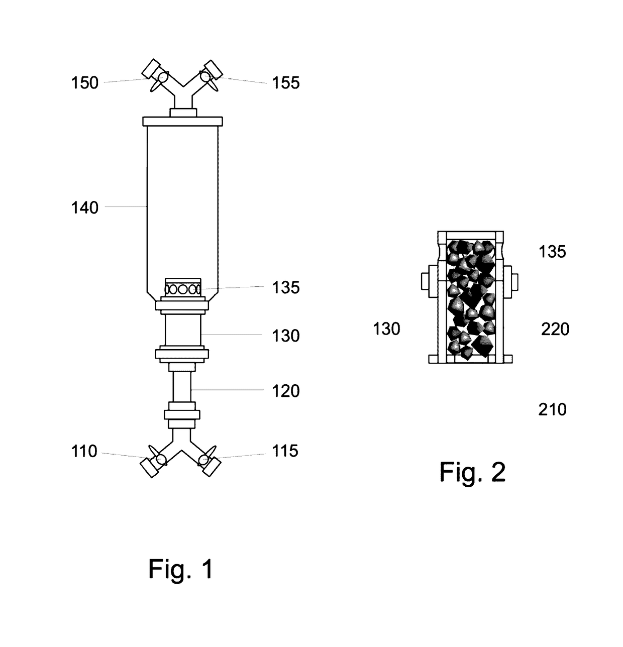
[0022]Basic components of a water-filtering apparatus that employs FWFC are illustrated by an embodiment depicted in FIGS. 1 and 2.

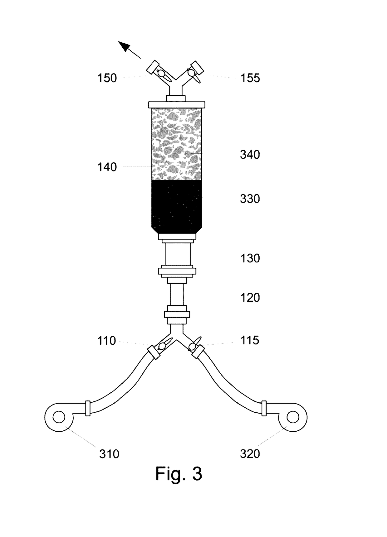
[0023]During a water-filtering cycle in the apparatus shown in FIGS. 1 and 2, a flow of water from below would pass upward through the following components:[0024](1) an open water-intake valve [110] while bypassing a closed air-intake valve [115][0025](2) an intake pipe [120][0026](3) an intake chamber [130] containing a threaded aperture [210] at its bottom that attaches to the intake pipe [120] and a matrix comprising a plurality of small chards of permanent magnets [220][0027](4) at least one portal hole [135] through the vertical wall of the cylindrically sh...


PUM

PropertyMeasurementUnit
speedsaaaaaaaaaa
permeableaaaaaaaaaa
gravityaaaaaaaaaa

Abstract

A fluid filtration system is disclosed herein. The filtration system includes a main tubular housing defining an interior chamber and having an outlet opening at a top end thereof and an inlet opening at a bottom thereof. A tubular inlet housing extends vertically into the interior chamber of the main housing through the inlet opening of the main housing. The tubular inlet housing has a hollow interior filled with shards of permanent magnets, a plurality of outlet portals located in the interior chamber proximate the bottom of the main housing, and an inlet opening at a bottom thereof. An inlet conduit is connected to the inlet opening of the tubular inlet housing. An adjustable fluid pump and can force the fluid from a supply of fluid to be filtered upwards through the inlet conduit at varying speeds. A permeable but compact horizontal layer of medium capable of trapping particulates is provided in the interior chamber of the main tubular housing adjacent the tubular inlet housing. The layer includes filtering particles that are attached to the magnets. Forces of magnetism produced by the shards of permanent magnets and gravity constrain the horizontal layer of filtering medium to maintain in place the layer of filtering particles. The adjustable fluid pump, an air pump connected to the inlet conduit, or electromagnets or vibrators mounted on an outer surface of the main housing can be used to disrupt the compactness of the layer of filtering particles to permit trapped particulates to be released and washed away from the layer of filtering particles.

Description

CROSS-REFERENCE TO A RELATED APPLICATION[0001]This utility application claims the benefit of U.S. Provisional Patent Application Ser. No. 62 / 176,533 filed Feb. 23, 2015, by Thomas Manaugh and Saïd Majdi, which is hereby incorporated by reference.STATEMENT REGARDING FEDERALLY SPONSORED RESEARCH OR DEVELOPMENT[0002]No federally sponsored research or development was used in the creation of this invention.BACKGROUND OF THE INVENTION[0003]Water, coming from a higher level than an artesian spring, can flow through a confined channel and travel upward into the spring as the water finds its own level. The upward-flowing water, if it passes through a layer of sand at the bottom of the spring, can be cleaned of solid particles by filtering action of the sand.[0004]Later, a faster flow of water could serve to disturb the sand and cause it to release the solid particles that had been trapped in the sand—thus cleaning the filtering sand. The release of filtered particles could also result from o...

Claims


Application Information

Patent Timeline
Patent Type & Authority Patents(United States)
IPC IPC(8): B01D24/26B01D24/30B01D24/12B01D24/00B01D35/06B01D24/16B01D24/46B01D39/06B01D46/00
CPCB01D46/0082B01D24/008B01D24/12B01D24/16B01D24/305B01D24/4621B01D24/4631B01D24/4673B01D35/06B01D39/06B01D46/79
Inventor MANAUGH, THOMAS SCOTTMAJDI, SAID OMAR
Owner MANAUGH THOMAS SCOTT
Learn More