
Transformer and spiral flat winding thereof

a transformer and spiral technology, applied in the direction of fixed transformers, magnets, magnetic bodies, etc., can solve the problems of increasing manufacturing costs, wasting a lot of working time on conventional windings, and unable to achieve desired electromagnetic effects, so as to reduce the time for assembling and the cost, and increase the product yield

Inactive Publication Date: 2010-03-11
LIEN CHANG ELECTRONICS ENTERPRISE
View PDF2 Cites 1 Cited by
  • Summary
  • Abstract
  • Description
  • Claims
  • Application Information

AI Technical Summary

Benefits of technology

[0008]The object of the present invention is to provide a transformer and its spiral flat winding. The assembling process can be performed simply and quickly. After the assembling process is completed, the respective coils of the winding are arranged tightly and orderly, thereby reducing the time for assembling and the cost. In this way, the product yield can be increased.
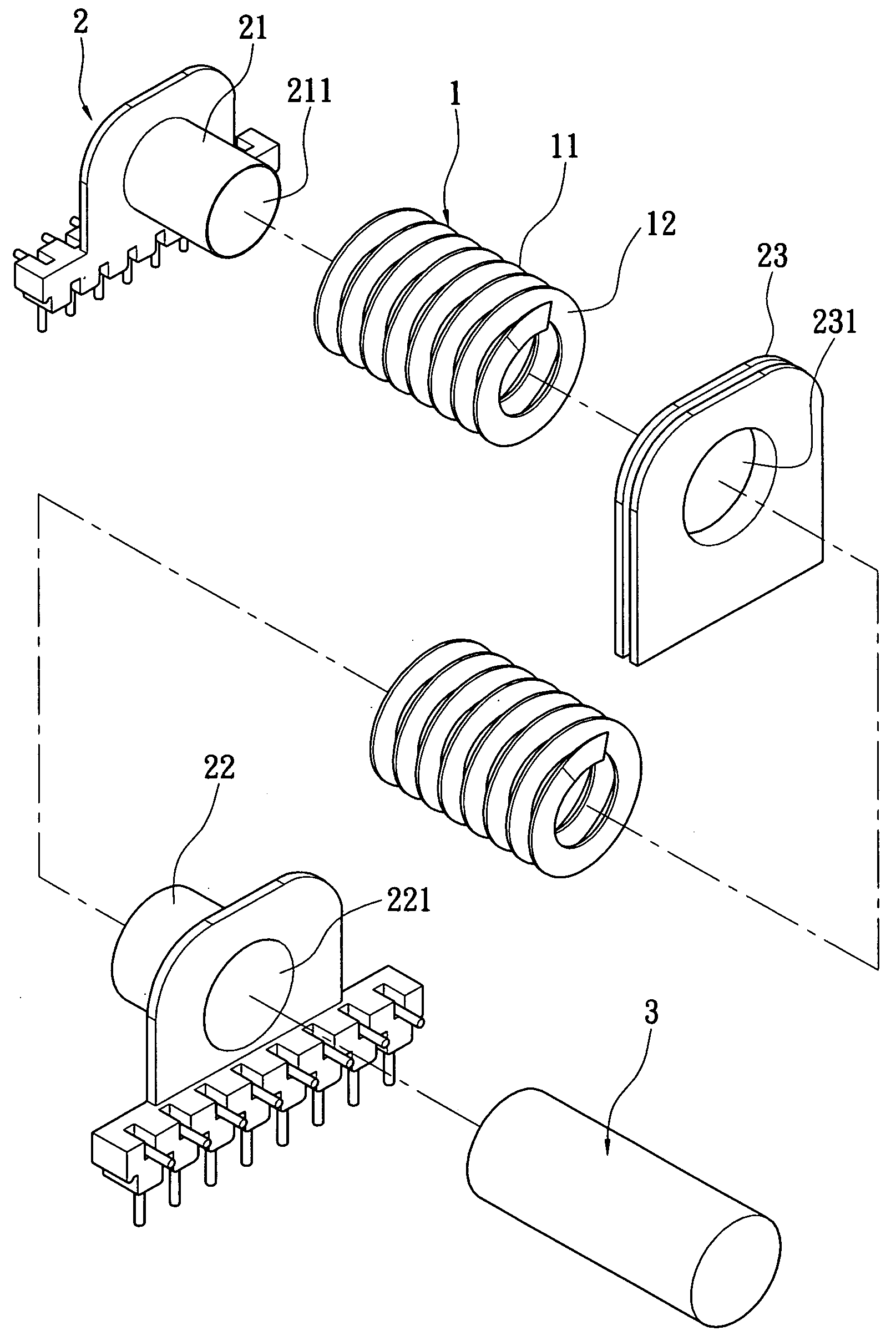
[0012]The present invention has advantageous features as follows. Since the spiral flat winding can surround the bobbin directly, the assembling process thereof can be performed simply and quickly. After the assembling process is completed, the respective coils are arranged tightly and orderly. Thus, the working hours for assembling and the cost can be reduced. As a result, the yield and profit of the products can be increased.

Problems solved by technology

Although the wire is wound around the bobbin, the gap between each winding must be kept tight otherwise the desired electromagnetic effect cannot be achieved.
Therefore, the conventional windings waste a lot of working time.
This drawback directly increases the manufacturing costs, and thus reduces the profit.

Method used


Image

  • Transformer and spiral flat winding thereof
  • Transformer and spiral flat winding thereof
  • Transformer and spiral flat winding thereof

Examples


Embodiment Construction

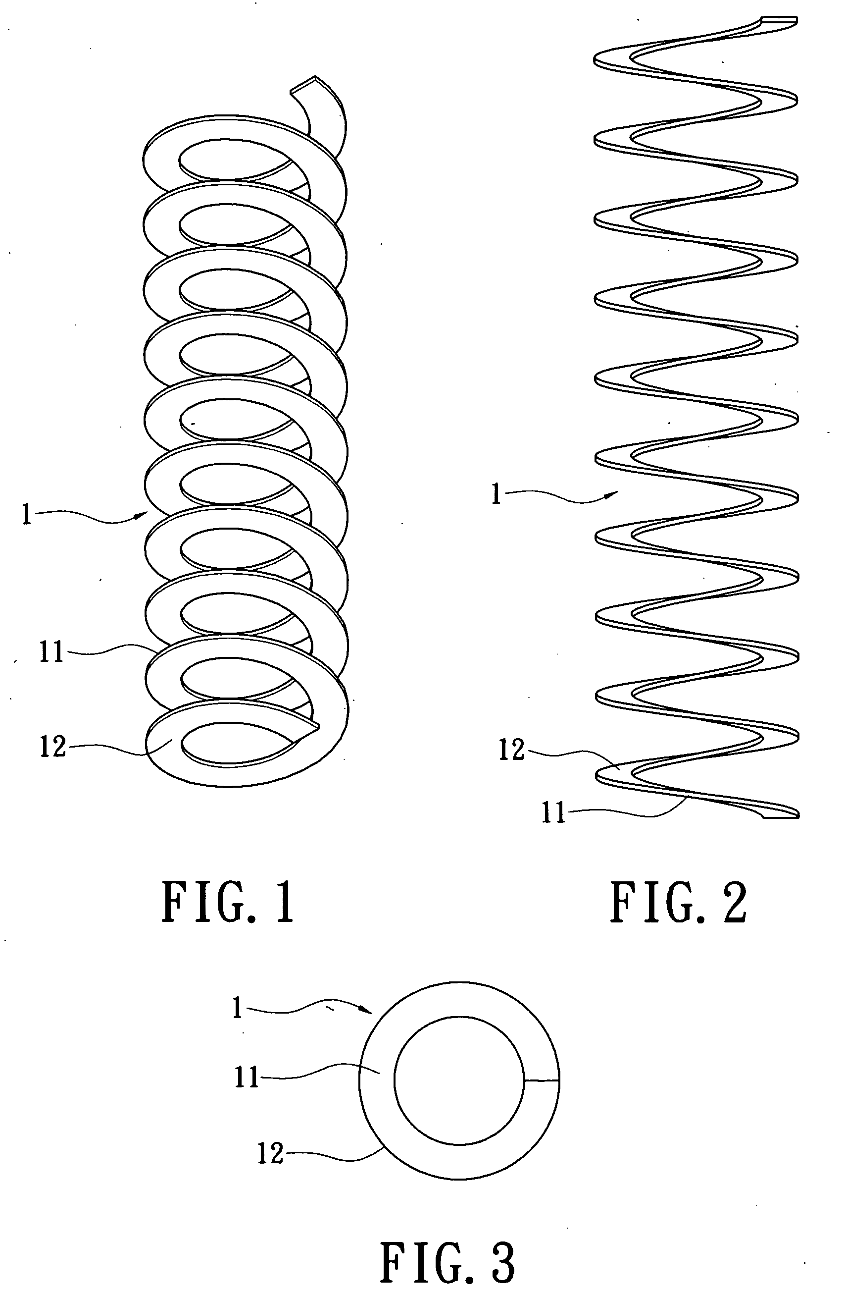
[0023]Please refer to FIGS. 1 to 3, which show the spiral flat winding 1 according to the first embodiment of the present invention. The spiral flat winding 1 is integrally formed from a copper sheet and has the shape of a spring, compressed such that its windings are close to each other (FIG. 8).

[0024]The surface of the spiral flat winding 1 has a cladding layer 12. The cladding layer 12 is made of an insulating material (such as an insulating paint) that can be coated on the surface of the spiral flat winding 1, thereby achieving a desired insulating effect.

[0025]In the present embodiment, each of the flat loops 11 is a circular flat sheet, and they are spirally formed into the flat winding.

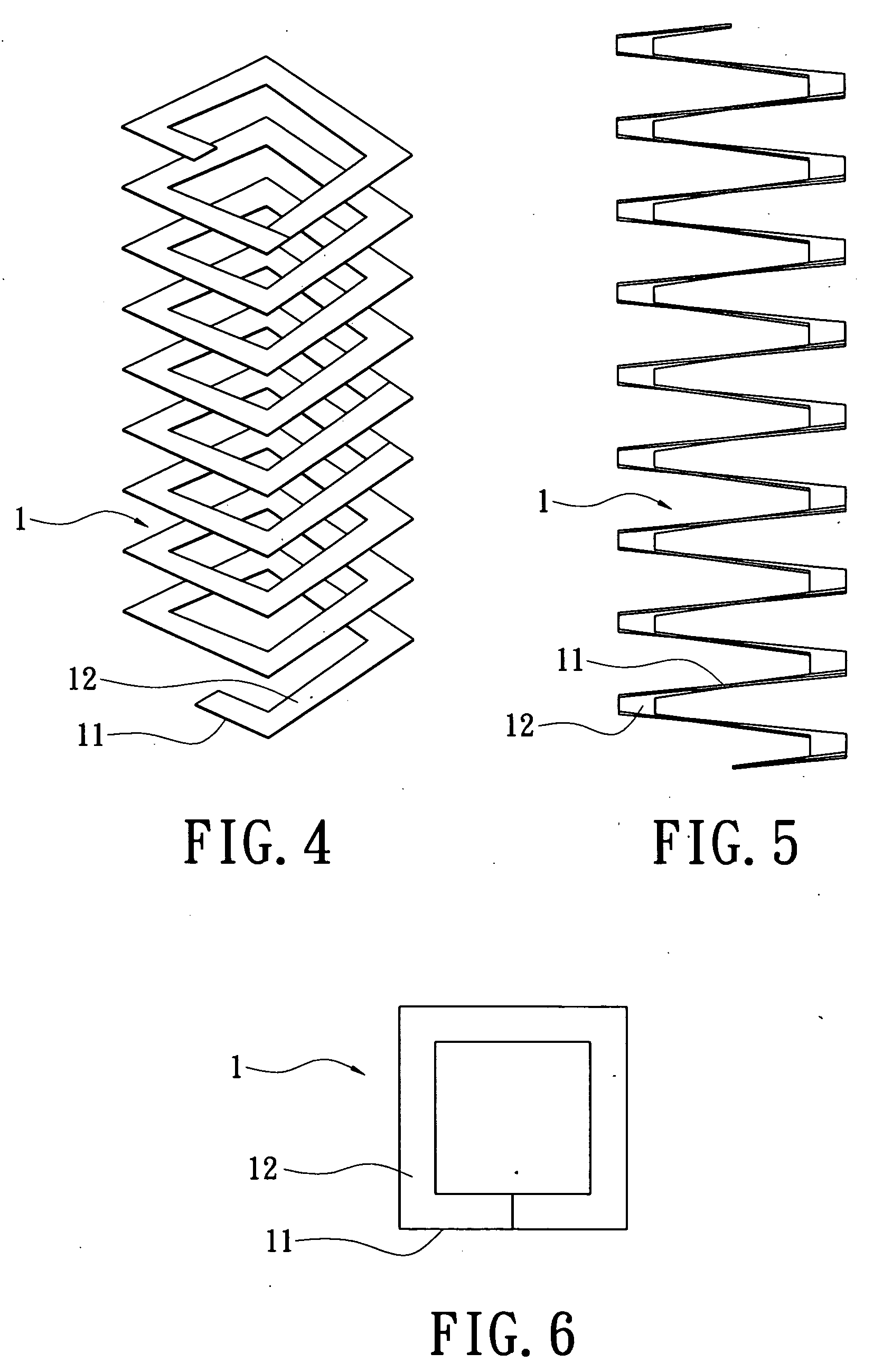
[0026]Please refer to FIGS. 4 to 6, which show the spiral flat winding 1 of the second embodiment of the present invention. Each of the flat loops 11 can be a rectangular flat sheet. Like the first embodiment, the flat loops 11 of the present embodiment can be connected to each other to form a ...


PUM

PropertyMeasurementUnit
magnetic fieldsaaaaaaaaaa
voltageaaaaaaaaaa
distancesaaaaaaaaaa

Abstract

A transformer includes a bobbin, an iron core and two spiral flat windings. The bobbin has a primary side portion, a secondary side portion and a separating plate. The separating plate is provided between the primary side portion and the secondary side portion. The first, second and third through holes are in communication with each other. The iron core penetrates the first, second and third through holes. The spiral flat winding is formed from a plurality of flat loops. The two spiral flat windings are provided on both sides of the separating plate and surround the primary side portion and the secondary side portion. Via the above arrangement, the spiral flat winding can be disposed around the bobbin, so that the assembling process can be performed simply and quickly. Thus, the working hours for assembling and the cost can be reduced.

Description

BACKGROUND OF THE INVENTION[0001]1. Field of the Invention[0002]The present invention relates to a transformer and the spiral flat winding thereof, and in particular to a transformer and the spiral flat winding thereof whereby a stepping-up, stepping-down or power-delivering process can be performed.[0003]2. Description of Related Art[0004]The transformer plays an important role in a power delivering system. The transformer can be used in power plants as well as in many electronic products available in the market. There are many types and ways of usage of transformers.[0005]A transformer is constituted of at least two sets of adjacent windings, in which the magnetic fields generated by the windings intersect. Via the transformer, a stepping-up or stepping-down process can be performed. The stepping-up transformer increases the voltage and reduces the current, thereby yielding the power suitable for transport over long distances. The stepping-down transformer is used to yield power t...

Claims


Application Information

Patent Timeline
Patent Type & Authority Applications(United States)
IPC IPC(8): H01F27/30H01F41/00
CPCH01F27/2847H01F30/06Y10T29/4902H01F2005/043H01F2017/046H01F2005/022
Inventor CHAN, CHUN-KONGCHI, DER-HO
Owner LIEN CHANG ELECTRONICS ENTERPRISE
Learn More