Fitment and overcap therefor

a technology of fitting and overcap, which is applied in the direction of caps, applications, liquid handling, etc., can solve the problems of unsatisfactory changes in product color, adversely affecting the product in the package,

Active Publication Date: 2017-04-04
APTARGROUP INC
View PDF80 Cites 8 Cited by
  • Summary
  • Abstract
  • Description
  • Claims
  • Application Information

AI Technical Summary

Benefits of technology

[0019]According to one general aspect of the invention, the fitment includes a spout that defines an access passage, an exterior sealing surface, and at least one laterally projecting shear member. The cap defines a skirt that extends over a portion of the spout. The skirt has a skirt sealing surface for engaging the fitment exterior sealing surface to create a seal when the cap and the fitment are in the initially assembled orientation. The cap further defines an aperture for initially receiving the shear member when the cap and fitment are in the initially assembled orientation. The cap also defines at least one frangible bridge that extends across a portion of the aperture for being severed by the shear member during relative rotation between the cap and fitment. The aperture and the shear member cooperate, when the cap and the fitment are in the initially assembled orientation and subjected to a flow of a sterilizing gas, to create turbulence in the sterilizing gas flow adjacent portions of the cap and the fitment to enhance sterilization thereof.

Problems solved by technology

Such adverse effects depend on the nature of the product, and can include undesirable changes in the product color, for example, or other characteristics.
Over time, oxygen (and / or other gases) can also pass from the external, ambient atmosphere through the wall of a closure spout and / or through the wall of a closure overcap, and then ultimately adversely affect a product in the package.

Method used


Image

  • Fitment and overcap therefor
  • Fitment and overcap therefor
  • Fitment and overcap therefor

Examples


Embodiment Construction

[0043]While this invention is susceptible of embodiment in different forms, this specification and the accompanying drawings disclose only some specific embodiments as examples of the invention. The invention is not intended to be limited to the embodiments so described, and the scope of the invention will be pointed out in the appended claims.

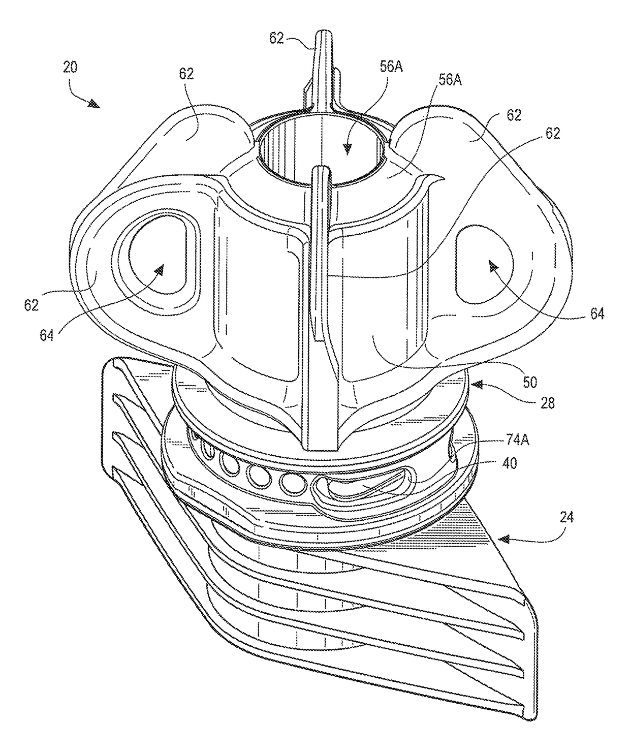
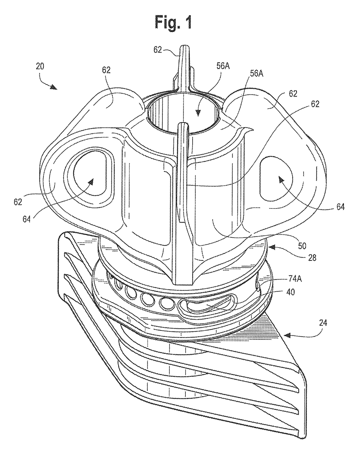
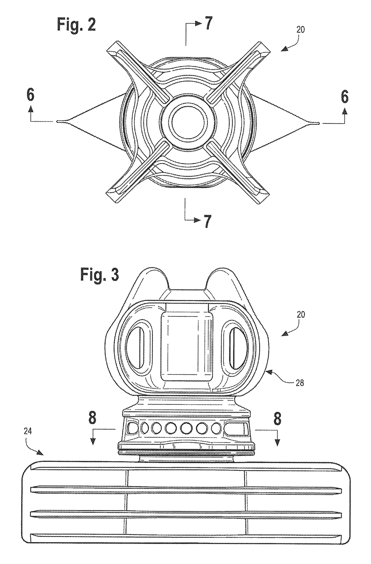
[0044]For ease of description, many figures illustrating the invention show a presently preferred embodiment of a closure assembly in the typical orientation that the closure assembly would have when it is installed at the opening of a container (which may be, for example, a flexible pouch), and terms such as upper, lower, inward, outward, axial, lateral, etc., are used with reference to this orientation. It will be understood, however, that the closure assembly may be manufactured, stored, transported, used, and sold in an orientation other than the orientation described.

[0045]The illustrated preferred embodiment of the closure assembly of th...


PUM

PropertyMeasurementUnit
distance D2aaaaaaaaaa
angle of rotationaaaaaaaaaa

Abstract

A closure assembly (20) that includes a cap or overcap (28) and a fitment (24) for a container is provided wherein the fitment (24) has a laterally projecting shear member (40), and the overcap (28) has an aperture (74) for initially receiving the shear member (40) when the overcap (28) and fitment (24) are in an initially assembled orientation or condition. The aperture (74) and the shear member (40) cooperate in the initially assembled orientation such that when subjected to a flow of a sterilizing gas, turbulence is created in the sterilizing gas flow to enhance sterilization of the combination. The closure assembly (20) may, instead, or additionally, be provided wherein the overcap (28) has an elongate, hollow plug (58) for establishing a first seal between the fitment (24) and the overcap (28) in the initially assembled orientation, and the wherein overcap (28) has a skirt (50) for establishing a second seal between the fitment (24) and the overcap (28) in the initially assembled orientation.

Description

CROSS-REFERENCE TO RELATED APPLICATION(S)[0001]Not Applicable.STATEMENT REGARDING FEDERALLY SPONSORED RESEARCH OR DEVELOPMENT[0002]Not applicable.REFERENCE TO A MICROFICHE APPENDIX[0003]Not applicable.TECHNICAL FIELD[0004]The present invention relates to a closure assembly that can be installed on a containment system (e.g., a container such as a pouch, carton, etc.) to provide (1) a spout extending from the containment system, and (2) a removable overcap therefor. The invention is particularly suitable for use with a handheld pouch containing a fluid product (e.g., a drink product, baby formula, yogurt, food additive, pharmaceutical product, etc.) wherein the closure assembly is initially provided to a packager for sterilization with a sterilizing gas so as to create an aseptic closure assembly that the packager can then install on the pouch.BACKGROUND OF THE INVENTION AND TECHNICAL PROBLEMS POSED BY THE PRIOR ART[0005]Various types of packages, including those that employ a flexib...

Claims


Application Information

Patent Timeline
Patent Type & Authority Patents(United States)
IPC IPC(8): B65D39/16B65D41/34B65D41/04B65D75/58B65D47/12B65D39/08
CPCB65D47/123B65D41/0485B65D41/34B65D75/5883B65D2101/0023B65D41/0421B65D2401/15
Inventor MAZURKIEWICZ, TIMOTHYWISNIEWSKI, JOHN
Owner APTARGROUP INC
Why Eureka
Try Eureka