Air sterilization system

a technology of air sterilization and air chamber, which is applied in the field of refrigeration, can solve the problems of increasing the incidence of cross contamination between food items, the fungi and bacteria in the refrigeration system that is used, and the increase of cross contamination of food items, so as to improve the air flow

Inactive Publication Date: 2008-02-19
MATIAS CARLOS J D
View PDF11 Cites 3 Cited by
  • Summary
  • Abstract
  • Description
  • Claims
  • Application Information

AI Technical Summary

Benefits of technology

[0005]The invention uses intense heat contained within capillaries to effectively kill micro-organisms such as mold, bacteria, and virus. Because the device operates without the release of large quantities of heat into the environment, it is particularly suited for use as part of an air sterilization system for a refrigerator, room, multi purpose chamber or compartment requiring air purification. When used inside a refrigeration chamber, the air sterilization system will reduce the development of smells, bacteria, spores and fungi inside the chamber to preserve and extend the shelf life of food products and stored materials.
[0007]Accordingly, it is an object of the invention to reduce airborne micro-organisms and of avoid the formation of smells, fungi, mold and bacteria in food-containing air chambers.
[0009]Another object of the invention is to provide an improved air sterilization system for refrigerators in which air sterilization assemblies including intake and outlet connections pass air in the refrigerator through the air sterilization assembly which kills fungus, bacteria and other airborne micro-organisms through heat.
[0010]Still a further object of the invention is to provide an improved air sterilization system for refrigerators which utilizes a fan to enhance the air flow through the air sterilizing assembly.
[0011]Yet still a further object of the invention is to provide an improved air sterilization system in which the air sterilization assembly is coupled to a cooling chamber so that the air from the cooling chamber passes through the sterilization system where the heat inside is used to kill the micro-organisms and the heat does not adversely affect the internal temperature of the cooling chamber.

Problems solved by technology

However, the refrigeration systems utilized do not inhibit the formation of fungi and bacteria inside the refrigerators and other cooling chambers.
These systems, however, have the drawback of increasing the incidence of cross contamination between food items when bacteria and spores are transported by air from one food item to another throughout the entire refrigeration chamber.

Method used


Image

  • Air sterilization system
  • Air sterilization system
  • Air sterilization system

Examples


Embodiment Construction

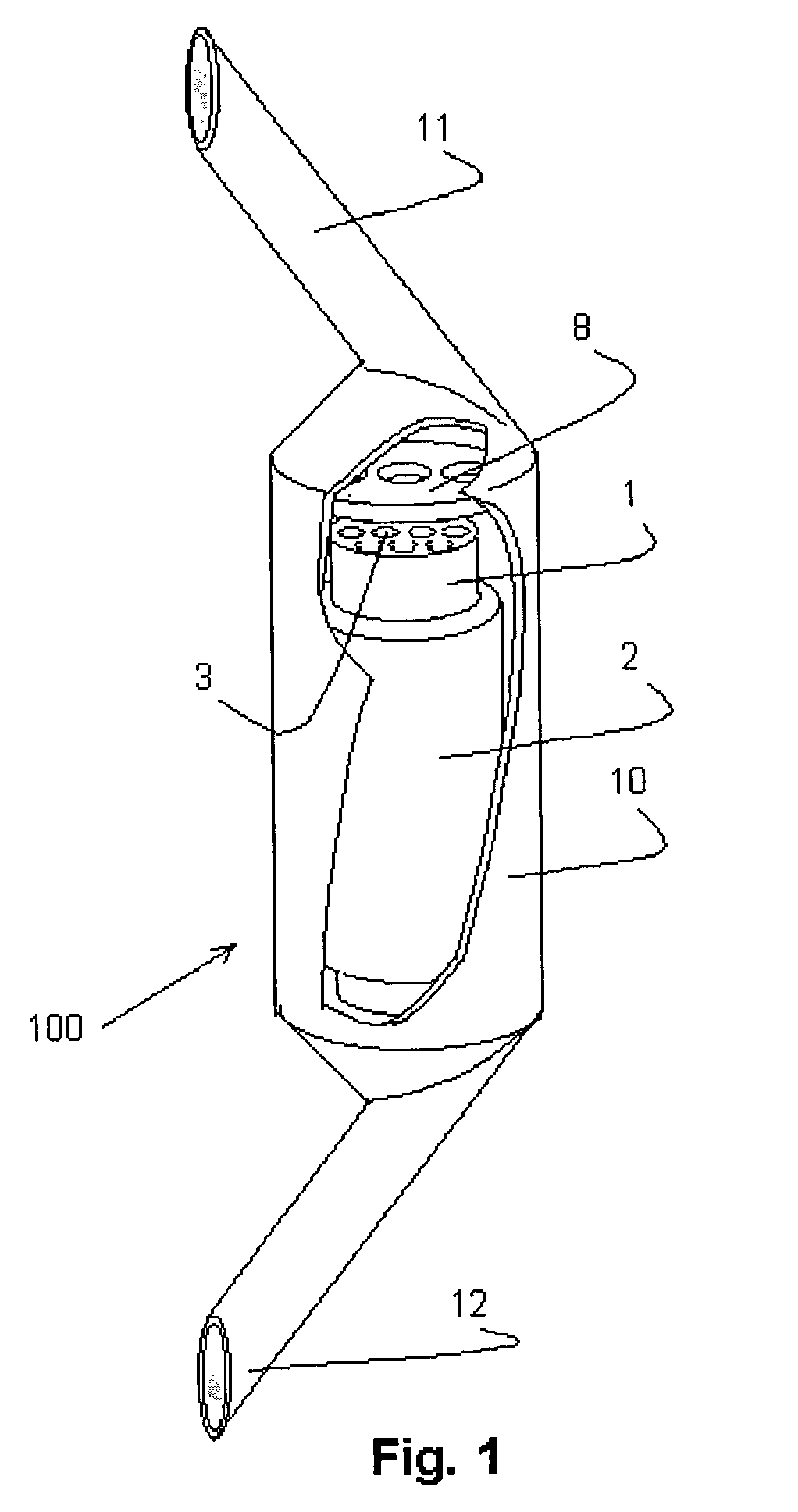
[0022]Reference is first made to FIG. 1 in which an air sterilizing assembly, generally indicated as 100, constructed in accordance with a preferred embodiment of the invention, is depicted. Air sterilizer assembly 100 has contaminated air entering by air convection at inlet 12. The air in sequence enters the sterilizing ceramic element 1 of the type shown and described in Applicant's prior U.S. Pat. No. 5,874,050, which is inserted in an optional insulated element 2. The hot sterilized air exhausts at the sterilizing element top end 3. The hot sterilized air is then cooled at optional heat exchanger 8. Finally the cooled, sterilized air exhausts air sterilizer chamber 10 through outlet 11 back to the refrigerator or chamber.

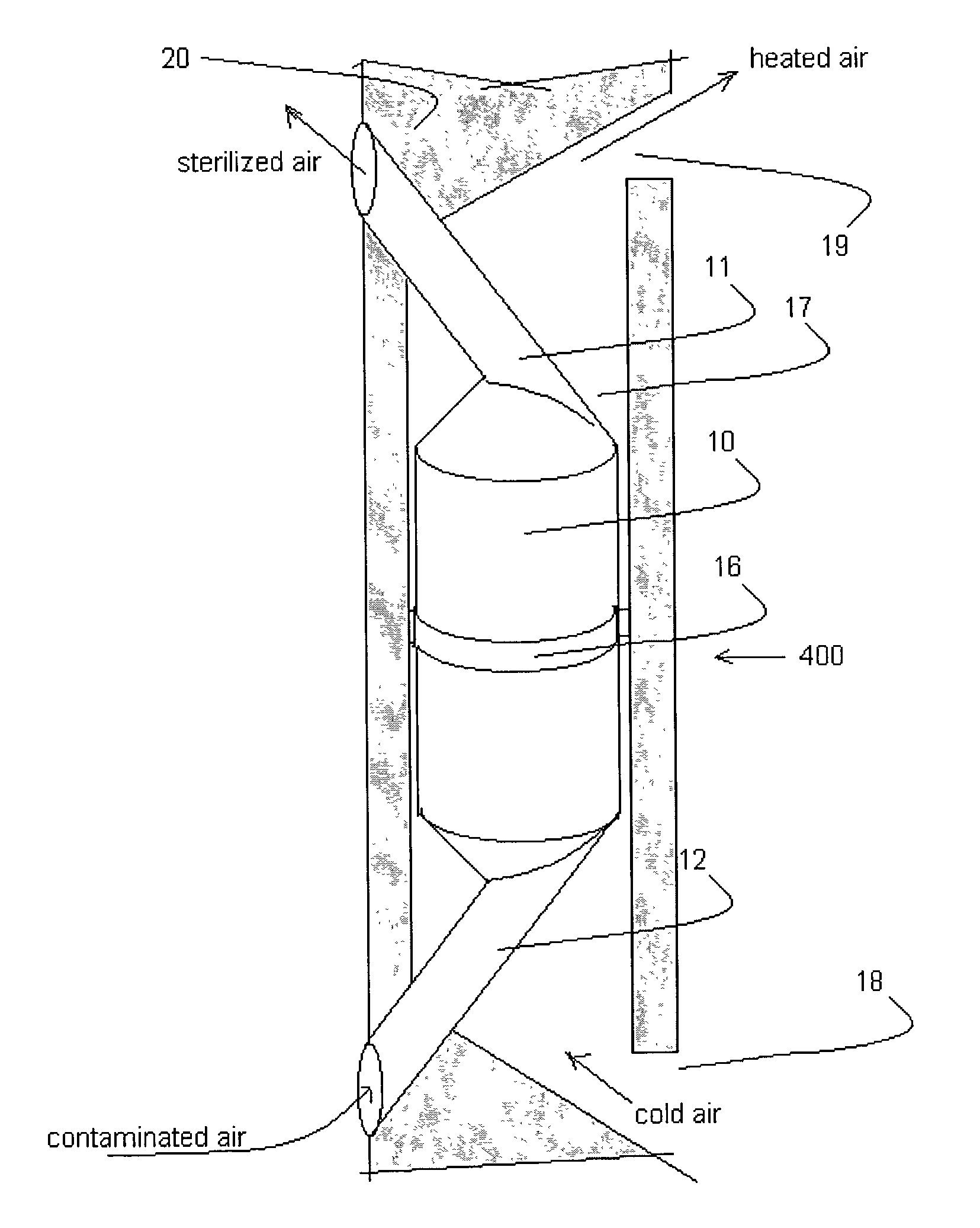
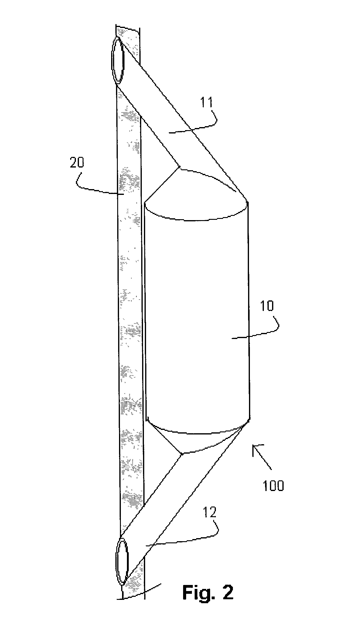
[0023]As shown in FIG. 2, like referenced elements being represented by like referenced numerals, air sterilization assembly 100 is affixed outside of the wall 20 of the chamber. As shown in FIG. 2, the left side of wall 20 is the interior of the chamber compart...


PUM

PropertyMeasurementUnit
temperatureaaaaaaaaaa
lengthaaaaaaaaaa
lengthaaaaaaaaaa

Abstract

An improved air sterilization system has unobstructed air passageways from a chamber substantially enclosing a volume of air to the air sterilization assembly unit in which the air sterilization assembly unit has heating elements located within air passageways in the unit to exterminate airborne micro-organisms by applying heat to the continuously flowing airstream, and in which the temperature of air leaving the system is insignificantly higher than the temperature of air entering the system.

Description

[0001]This invention is based upon provisional patent application No. 60 / 330,048, entitled Refrigerator Air Sterilization Device, filed 17 Oct. 2001; and provisional patent application No. 60 / 330,050, entitled Room Air Sterilization Device, filed 17 Oct. 2001. The priority date for these provisional patent applications is claimed herein.BACKGROUND OF THE INVENTION[0002]Since the beginning of the refrigeration industry there have been improvements in the preservation of food products and other heat sensitive products. However, the refrigeration systems utilized do not inhibit the formation of fungi and bacteria inside the refrigerators and other cooling chambers. More recently, some refrigerators have presented new interior air circulation systems that improve the refrigeration of food products by maintaining a constant flow of cold air of essentially constant temperature which keeps foods at a desired constant temperature. These systems, however, have the drawback of increasing the ...

Claims


Application Information

Patent Timeline
Patent Type & Authority Patents(United States)
IPC IPC(8): A61L9/16F25D17/04
CPCA61L9/16F25D17/042F24F2003/1664F25D2317/041F24F8/20Y02A50/20
Inventor MATIAS, CARLOS J. D.
Owner MATIAS CARLOS J D
Why Eureka
Try Eureka