
Capacitive touch panel

a capacitive touch panel and capacitive technology, applied in the field of capacitive touch panels, can solve the problems of poor multi-touch sensing performance of poor multi-touch sensing performance of the touch panel tp, etc., to achieve enhanced signal uniformity, effective inhibition of reverse signals, and enhanced multi-touch sensing performance of the on-cell capacitive touch panel

Inactive Publication Date: 2017-04-04
RAYDIUM SEMICON
View PDF5 Cites 0 Cited by
  • Summary
  • Abstract
  • Description
  • Claims
  • Application Information

AI Technical Summary

Benefits of technology

This design effectively reduces reverse signals, maintaining touch signal integrity even with multiple touch points at the same axis, thereby enhancing the multi-touch sensing performance of the on-cell capacitive touch panel.

Problems solved by technology

It should be noticed that the laminated structure 2 shown in FIG. 2 having no cover lens 18 and OCA / OCR 16 can achieve the effects of simple laminated structure, reducing thickness, and saving costs; however, stronger reverse signals will be generated accordingly and multi-touch sensing performance of the on-cell capacitive touch panel will become poor.
However, two touch points P3 and P4 in FIG. 4 are located at the same axis of the touch panel TP having the laminated structure 2, the reverse signals are generated at a third location R3 and a fourth location R4 on the touch panel TP respectively, and the third location R3 and the fourth location R4 will overlap the two touch points P3 and P4; therefore, the reverse signals generated will cancel out the touch signals of the two touch points P3 and P4, and the multi-touch sensing performance of the touch panel TP will become poor.

Method used


Image

  • Capacitive touch panel
  • Capacitive touch panel
  • Capacitive touch panel

Examples


Embodiment Construction

[0041]A preferred embodiment of the invention is an on-cell capacitive touch panel.

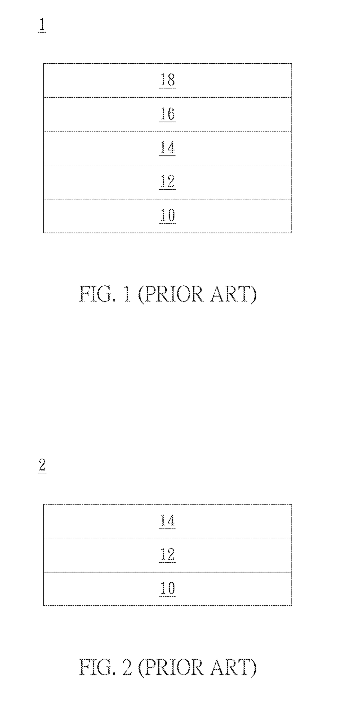
[0042]In this embodiment, the laminated structure of the on-cell capacitive touch panel can have no cover lens and OCA / OCR as the laminated structure 2 shown in FIG. 2, but not limited to this.

[0043]As shown in FIG. 2, the laminated structure 2 includes a LCD module 10, a touch sensing module 12, and a polarizing module 14. The touch sensing module 12 is disposed on the LCD module 10; the polarizing module 14 is disposed on the touch sensing module 12. In fact, the polarizing module 14 can be a polarizer or polarizing film, but not limited to this.

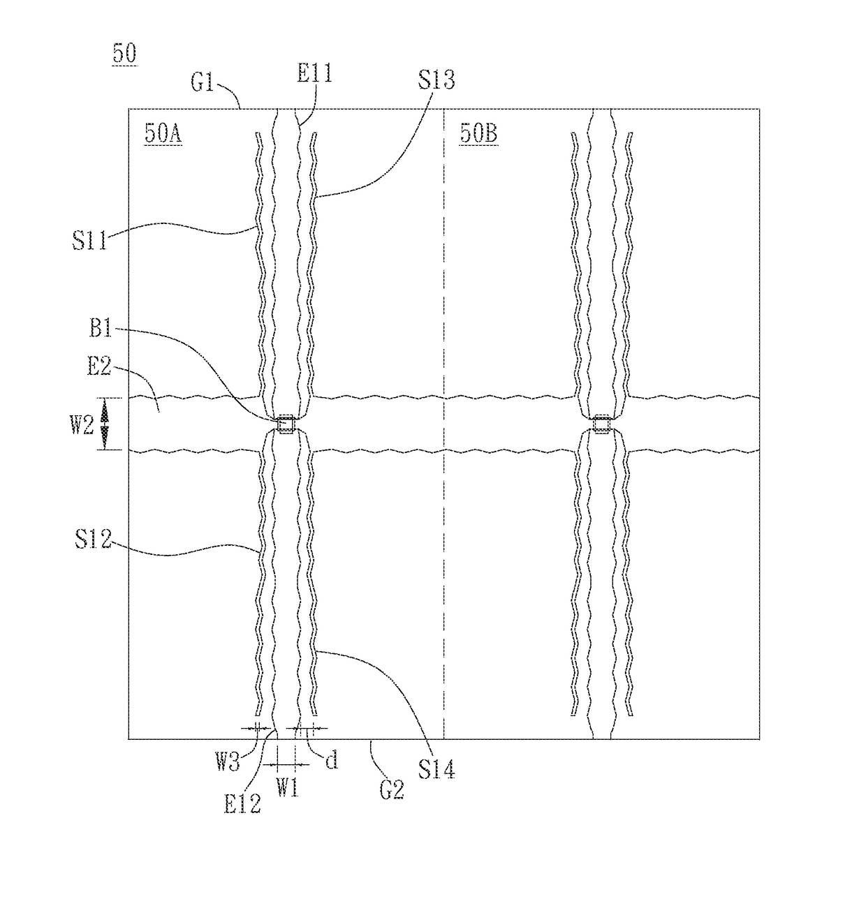
[0044]Please refer to FIG. 5. FIG. 5 illustrates a schematic diagram of the on-cell capacitive touch panel 5 having the same touch sensor patterns 50 in a preferred embodiment of the invention. As shown in FIG. 5, in the laminated structure of the on-cell capacitive touch panel 5, the touch sensing module includes nine same touch sensor patterns 50 arranged ...


PUM


Abstract

An on-cell capacitive touch panel is disclosed. Its laminated structure includes a LCD module, a touch sensing module, and a polarizing module. The touch sensing module is disposed on the LCD module. The polarizing module is disposed on the touch sensing module. The touch sensing module includes a touch sensor pattern having a single-layer ITO structure. The touch sensor pattern includes a first pattern unit and a second pattern unit which are the same and both have at least one first electrode, second electrode, and extending electrode. The first electrode is arranged along a first direction and the second electrode is arranged along a second direction. The first direction and second direction are vertical. The first electrode crosses the second electrode via a bridge structure. The extending electrode surrounds the first electrode and it is arranged along the first direction.

Description

BACKGROUND OF THE INVENTION[0001]Field of the Invention[0002]This invention relates to a touch panel, especially to an on-cell capacitive touch panel capable of effectively inhibiting reverse signals and enhancing signal uniformity.[0003]Description of the Related Art[0004]In general, there are several different laminated structures of the capacitive touch panel. For example, in an on-cell capacitive touch panel, touch sensors are disposed on the outer surface of the glass of the display panel, so that display function and touch function can be integrally provided, and the laminated structure of the on-cell capacitive touch panel can become simpler. If the on-cell capacitive touch panel has no cover lens, the user can directly perform touch operation on the display panel.[0005]Please refer to FIG. 1 and FIG. 2. FIG. 1 and FIG. 2 illustrate two different laminated structures of the on-cell capacitive touch panel respectively. The difference between the laminated structure 1 shown in ...

Claims


Application Information

Patent Timeline
Patent Type & Authority Patents(United States)
IPC IPC(8): G06F3/044
CPCG06F3/044G06F2203/04104G06F3/0443G06F3/0446G02F1/13338G02F1/133528G02F1/134309G02F1/13439G06F3/0412G06F2203/04111G06F2203/04113
Inventor LIN, YI-YINGLIN, KUAN-MINGSHIEH, HSIN-WEILEE, KUN-PEI
Owner RAYDIUM SEMICON
Features
  • Generate Ideas
  • Intellectual Property
  • Life Sciences
  • Materials
  • Tech Scout
  • Unparalleled Data Quality
  • Higher Quality Content
  • 60% Fewer Hallucinations
Learn More