Guide vane arrangement and method for mounting a guide vane

a technology of guide vane and inner ring, which is applied in the direction of engine components, leakage prevention, stators, etc., can solve the problems of large structural space for the components that are required for the movable bearing of the guide vane on the inner ring segmen

Inactive Publication Date: 2017-04-11
MTU AERO ENGINES GMBH
View PDF13 Cites 0 Cited by
  • Summary
  • Abstract
  • Description
  • Claims
  • Application Information

AI Technical Summary

Benefits of technology

[0006]An object of the present invention is to provide an improved turbomachine having at least one guide vane arrangement. Another object of the present invention is to provide, in particular, a guide vane that requires less structural space for the fixing in place or bearing on the inner ring segment. Additionally or alternatively, another object of the present invention is to provide a method by means of which the guide vane can be connected in a simple way to the inner ring segment.

Problems solved by technology

It is a particular disadvantage in the above-named connection that the components that are required for the movable bearing of the guide vane on the inner ring segment require a large structural space.

Method used


Image

  • Guide vane arrangement and method for mounting a guide vane
  • Guide vane arrangement and method for mounting a guide vane
  • Guide vane arrangement and method for mounting a guide vane

Examples


first embodiment

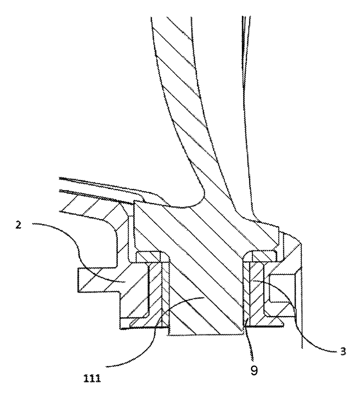
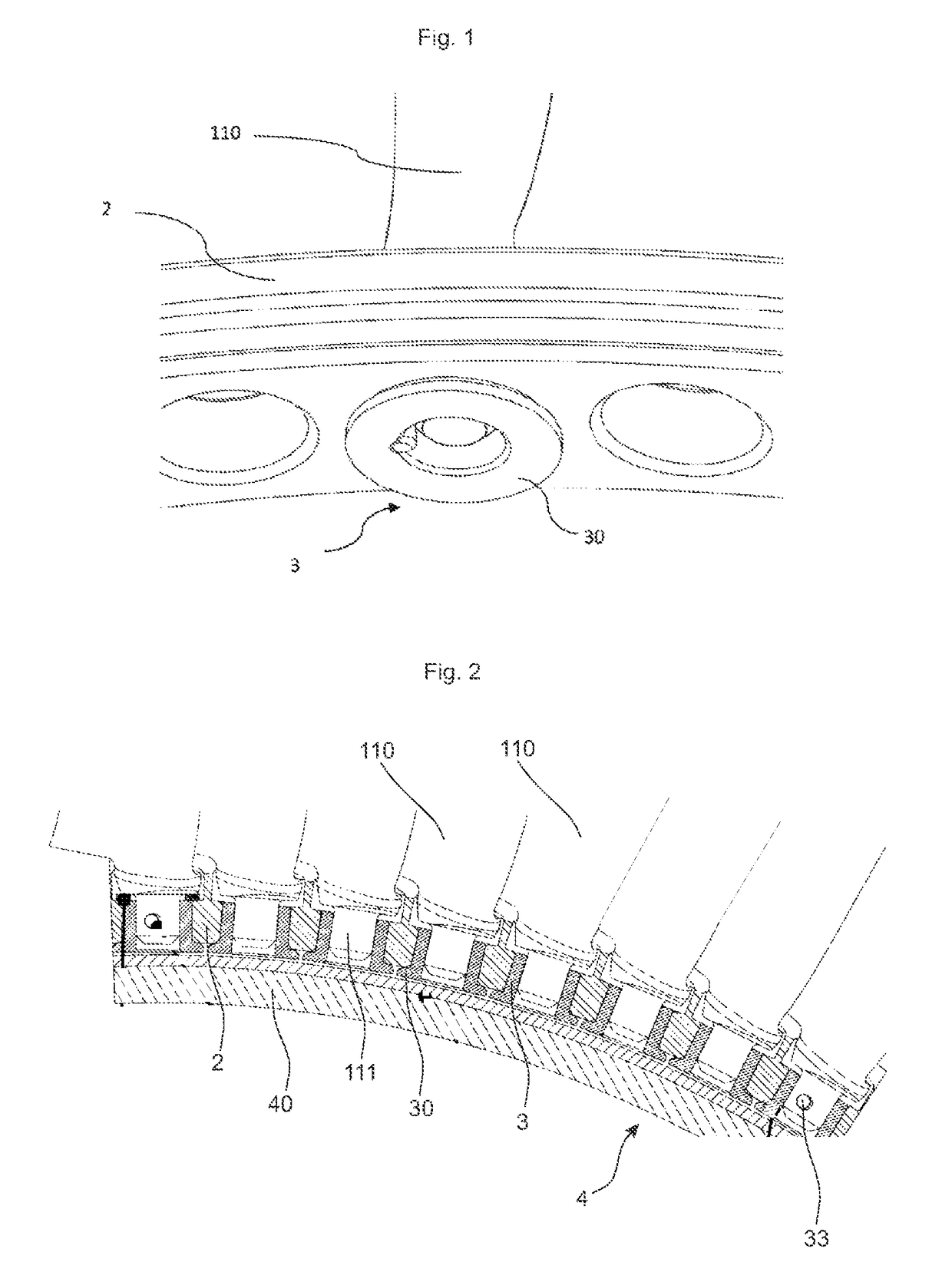
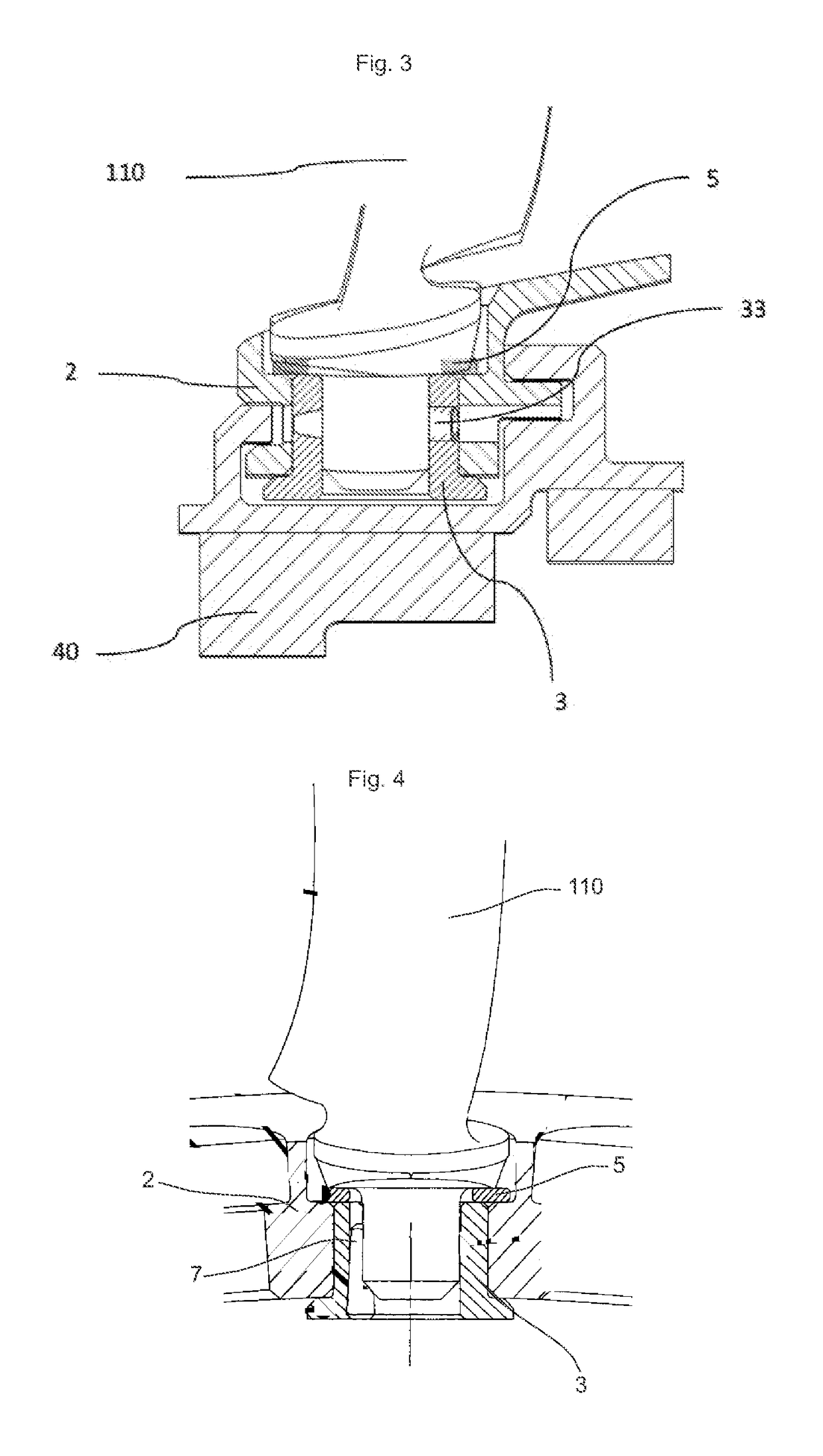
[0037]A screw locking device is provided in order to prevent an unscrewing of the screw connection between the journal 111 and the bushing 3. Therefore, the screw locking device serves for preventing a relative movement between the journal 111 and the bushing 3. The screw locking device which is shown in FIG. 3, corresponds to a split pin locking device. For producing the split pin locking device, a recess is provided in the bushing 3, the journal 111, and a portion of the inner ring segment 2, in which or through which a split pin 33 can be introduced in order to produce the named locking device.

second embodiment

[0038]A screw locking device is shown in FIG. 4. The screw locking device has a locking pin 7, which is inserted into an intermediate space between the journal 111 and the bushing 3. A threaded sleeve 9, as in FIG. 6, and / or a nut 12, as in FIG. 7, may be employed to help secure the bushing 3 relative to journal 111.

third embodiment

[0039]A screw locking device is shown in FIG. 5. In this embodiment, the screw locking device has a locking wire 8. The locking wire 8 is disposed in uptakes in the bushing 3 and is coupled to the journal 111.


PUM

PropertyMeasurementUnit
rotation-resistantaaaaaaaaaa
rotationaaaaaaaaaa
widthaaaaaaaaaa

Abstract

The invention relates to a guide vane arrangement and a method for mounting a guide vane. The guide vane arrangement has at least one guide vane having a radially inner journal, which engages in a borehole of a bushing. The bushing is disposed in a borehole of an inner ring segment. The journal is connected to the bushing in a rotation-resistant manner and a slide mounting is provided between the bushing and the inner ring borehole. For mounting the guide vane in an inner ring segment, the journal of the guide vane is introduced into the borehole of the bushing. Further, the journal is fastened to the bushing in a rotation-resistant manner, and the bushing is slide-mounted with the inner ring segment. The slide mounting is conducted prior to or simultaneously with or after the fastening of the journal to the bushing in a rotation-resistant manner.

Description

BACKGROUND OF THE INVENTION[0001]The invention relates to a guide vane for guide vane arrangement, and a method for fastening or mounting such a guide vane.[0002]A multiple number of differently designed turbomachines are already known from the prior art. Turbomachines have a housing through which a flow can pass axially, on which at least one guide vane ring is fastened, which has a plurality of guide vanes disposed next to one another in the peripheral direction. On their radially inner end, the guide vanes have an end segment, which can be joined with a seal support in a detachable manner. The seal support serves for sealing a gap between the guide vane, in particular, the end segment, and a rotor of the turbomachine.[0003]Guide vanes that can be adjusted about their longitudinal axis, are connected in a movable manner on their radial end to an inner ring segment as an end section. According to internal company practice, a radially inner end of the guide vane, such as, for exampl...

Claims


Application Information

Patent Timeline
Patent Type & Authority Patents(United States)
IPC IPC(8): F01D9/02F01D17/16F01D11/00
CPCF01D9/02F01D17/162F01D11/001F05D2230/60Y10T29/49321
Inventor KLAEN, STEPHANSCHINKO, NORBERT
Owner MTU AERO ENGINES GMBH
Why Eureka
Try Eureka