Radar apparatus

a technology of radar and detector, applied in the field of radar apparatus, can solve the problems of difficult detection of phase differences, affecting direction estimation, and errors according to detection errors, so as to suppress the deterioration of target direction estimation performan

Active Publication Date: 2017-04-11
PANASONIC CORP
View PDF26 Cites 10 Cited by
  • Summary
  • Abstract
  • Description
  • Claims
  • Application Information

AI Technical Summary

Benefits of technology

[0009]One non-limiting and exemplary embodiment provides a radar apparatus that detects a reflection signal from a static target located at a side of a moving body on the basis of deviations in Doppler frequency and that performs reception array correction on the basis of the direction of arrival of the reflection signals from the still target, in order to suppress deterioration of the accuracy of correcting amplitude and phase deviations between reception antennas included in an array antenna.
[0011]According to the present disclosure, by detecting a reflection signal from a static target located at a side of a moving body on the basis of deviations in Doppler frequency and performing reception array correction on the basis of the direction of arrival of the reflection signal from the static target, the accuracy of estimating the direction of arrival of a reflection signal from an object can be suppressed and, accordingly, deterioration of target direction estimation performance can be suppressed.

Problems solved by technology

Here, because phase differences including deviations between the reception antennas are detected, it is difficult to accurately detect phase differences deriving from the direction of arrival of a reflection signal from the object, which is problematic.
Therefore, detection of phase deviations performed for reception array correction includes errors and, as a result, errors according to the errors in the detection affect estimation of the direction of arrival of a reflection signal from a target.

Method used


Image

  • Radar apparatus
  • Radar apparatus
  • Radar apparatus

Examples


first embodiment

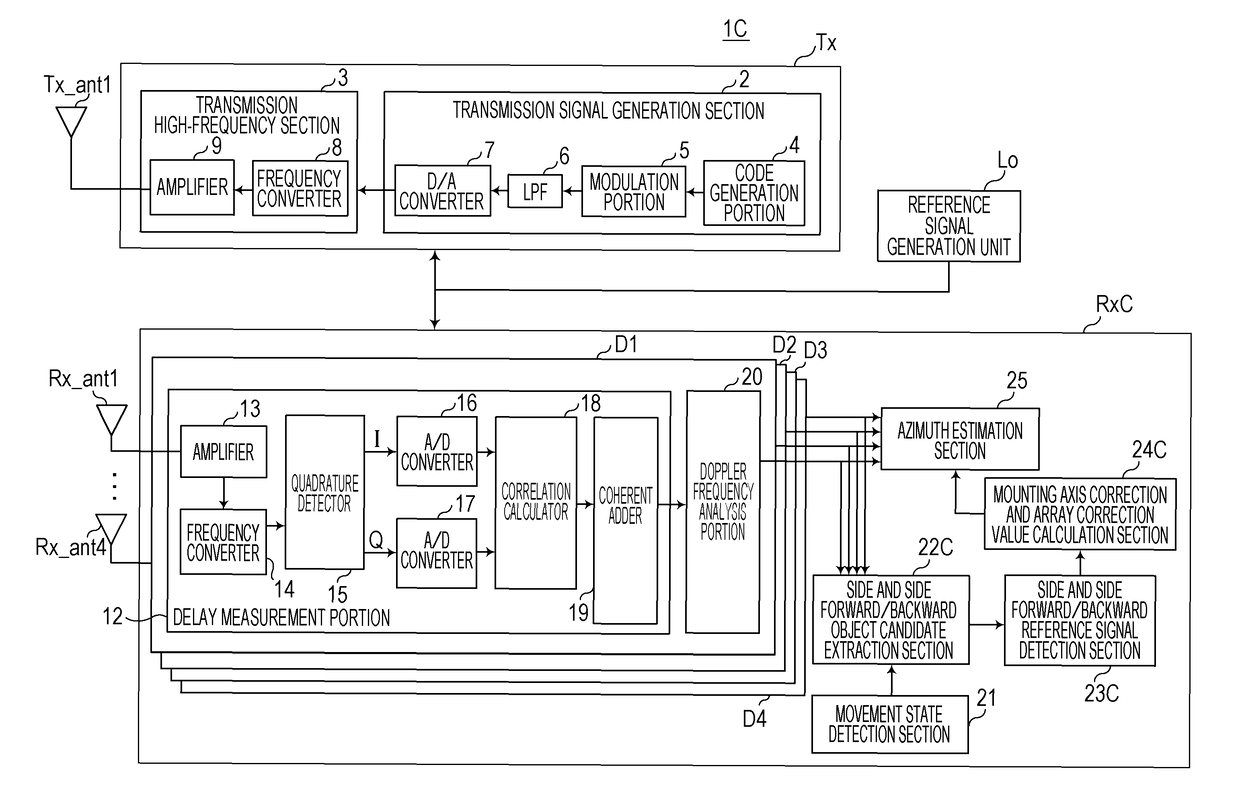
[0025]FIG. 1 is a diagram illustrating a relationship between a vehicle coordinate system and a radar coordinate system viewed from above. In a first embodiment, for example, the vehicle CR includes two radar apparatuses 1L and 1R at front left and right corners thereof, respectively, relative to a forward direction FR, but the vehicle CR may include two radar apparatuses at rear left and right corners thereof.

[0026]In FIG. 1, a mounting angle γ of a plurality of reception antennas (hereinafter referred to as an “array antenna”) of the radar apparatus 1L is the angle of a direction LC perpendicular to an opening of an array antenna LAR of the radar apparatus 1L relative to a left direction LH of the vehicle CR, which is a reference mounting angle of the left radar apparatus 1L. The mounting angle γ of the array antenna LAR of the radar apparatus 1L increases clockwise (γ>0) from the reference angle (0 [rad]), which is the left direction LH of the vehicle CR. The direction LC perpend...

second embodiment

[0173]In a second embodiment, a radar apparatus 1A including a radar transmission unit TxA that switches a main beam direction of a radar transmission signal instead of the radar transmission unit Tx of the radar apparatus 1 according to the first embodiment will be described with reference to FIG. 7. The radar apparatus 1A according to the second embodiment may be applied to a radar apparatus C according to a fourth embodiment, which will be described later (refer to a radar apparatus 1D illustrated in FIG. 11).

[0174]FIG. 7 is a diagram illustrating the internal configuration of the radar apparatus 1A according to the second embodiment. The radar apparatus 1A illustrated in FIG. 7 includes the reference signal generation unit Lo, a transmission beam control unit Be, the radar transmission unit TxA, and a radar reception unit RxA. Description of the radar apparatus 1A according to this embodiment that is the same as description of the radar apparatus 1 according to the first embodim...

third embodiment

[0190]In a third embodiment, a radar apparatus 1B that repeatedly transmits a radar transmission signal (for example, chirped pulses of a frequency-modulated continuous wave (FMCM)) subjected to frequency modulation performed by a radar transmission unit TxB will be described with reference to FIGS. 8, 9A, and 9B.

[0191]FIG. 8 is a diagram illustrating the internal configuration of the radar apparatus 1B according to the third embodiment in detail. FIG. 9A is a diagram illustrating a relationship between a frequency-modulated transmission signal and transmission periods. FIG. 9B is a diagram illustrating a reflection reception signal, which is the frequency-modulated transmission signal illustrated in FIG. 9A reflected from a static target or a moving target. Description of the radar apparatus 1B according to this embodiment that is the same as description of the radar apparatus 1 according to the first embodiment is simplified or omitted, and differences will be mainly described.

[01...


PUM


Abstract

Each of antenna system processors of a radar receiver generates, through correlation calculation of a reflection signal and a radar transmission signal, an array correlation signal for each delay in arrival of the reflection signal at each Doppler frequency. A static target candidate extractor extracts, on the basis of outputs of the antenna system processors and a Doppler frequency of a reflection signal from a static target located at a side of a moving body, array correlation signals corresponding to a candidate for the static target. A reference signal detector outputs a reference signal regarding the side of the moving body using, among the outputs of the static target candidate extractor, array correlation signals whose consistency is high. A correction value calculator calculates, using outputs of the reference signal detector, a correction value for correcting deviations between reception antennas included in an array antenna.

Description

BACKGROUND[0001]1. Technical Field[0002]The present disclosure relates to a radar apparatus mounted on a moving body such as a vehicle.[0003]2. Description of the Related Art[0004]A radar apparatus that receives a reflection signal from a target (hereinafter also referred to as an object) using a plurality of reception antennas included in an array antenna and that estimates the direction of arrival of the reflection signal from the object within a wide-angle range on the basis of phase differences between the reception signal received by the reception antennas is known.[0005]In order to estimate the direction of arrival of a reflection signal from an object using an array antenna, amplitude and phase deviations between reception antenna systems caused in antenna elements included in the reception antenna systems, radio frequency (RF) circuits that handle high-frequency signals, and analog baseband circuits that handle baseband signals need to be corrected (hereinafter referred to a...

Claims


Application Information

Patent Timeline
Patent Type & Authority Patents(United States)
IPC IPC(8): G01S13/93G01S13/34G01S13/32G01S13/26G01S7/41G01S7/35G01S13/58G01S7/40G01S7/292G01S7/288G01S7/28G01S13/931
CPCG01S13/931G01S7/2923G01S7/40G01S7/4026G01S7/411G01S7/414G01S7/415G01S13/26G01S13/325G01S13/343G01S13/582G01S7/2813G01S7/292G01S7/354G01S13/93G01S2007/2886G01S2013/9375G01S2013/9385G01S2013/93274G01S2013/93271G01S7/2886
Inventor KISHIGAMI, TAKAAKINISHIMURA, HIROFUMI
Owner PANASONIC CORP
Why Eureka
Try Eureka