Light beam scanning device and image forming apparatus that perform light amount control

a scanning device and light beam technology, applied in the direction of electrographic process equipment, printing, instruments, etc., can solve the problems of increasing the size of the light source of the image forming apparatus, insufficient time to complete automatic power control, and inability to perform light amount control of each light beam with accuracy, etc., to achieve the effect of suppressing the lowering of light amount control accuracy

Inactive Publication Date: 2012-07-26
CANON KK
View PDF4 Cites 4 Cited by
  • Summary
  • Abstract
  • Description
  • Claims
  • Application Information

AI Technical Summary

Benefits of technology

[0012]The present invention provides a light beam scanning device and an image forming apparatus that are capable of suppressing lowering of accuracy of light amount control executed when scanning a photosensitive member using a plurality of light beams.

Problems solved by technology

Then, it is required to increase the distance between light emitting elements that emit the adjacent light beams, which increases the size of the light source of the image forming apparatus.
On the other hand, if a plurality of light emitting elements are disposed such that the space interval between each adjacent ones of light beams in the scanning direction thereof is made narrower than the width of a photodiode, and the automatic power control is performed by lighting the plurality of light emitting elements in the order of arrangement thereof, adjacent light beams simultaneously enter the photodiode, which makes it impossible to perform light amount control of each light beam with accuracy.
However, at the time of starting the automatic power control of the light beam from the second light emitting element, the light beam has already come to a point where it has entered the photodiode, and there is not sufficient time to complete the automatic power control before this light beam terminates scanning of the photodiode.

Method used


Image

  • Light beam scanning device and image forming apparatus that perform light amount control
  • Light beam scanning device and image forming apparatus that perform light amount control
  • Light beam scanning device and image forming apparatus that perform light amount control

Examples


first embodiment

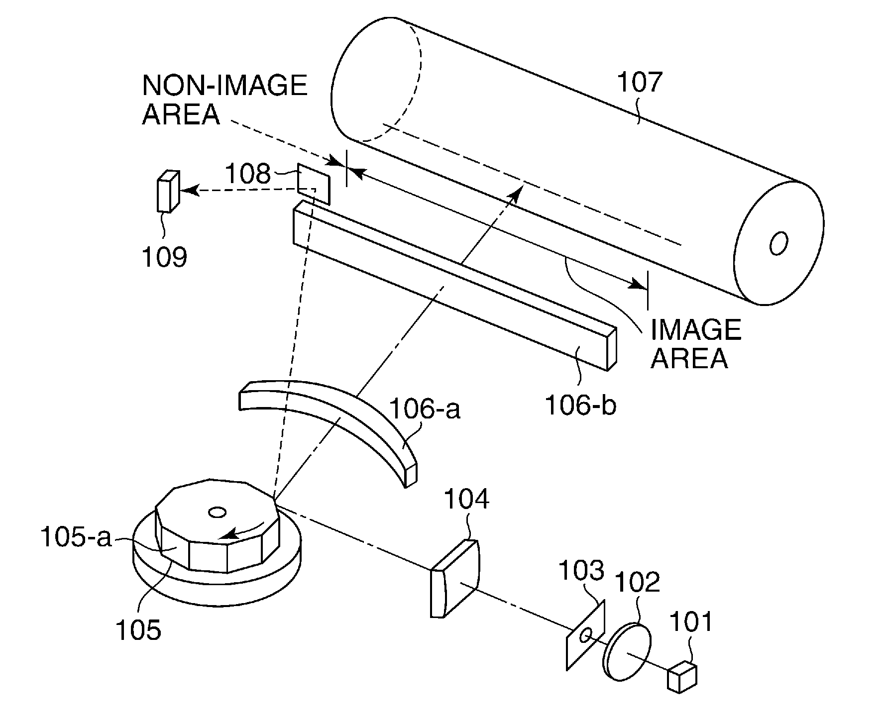
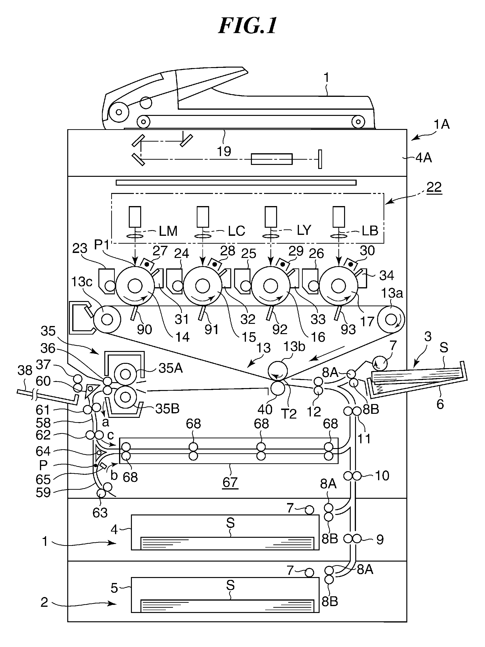
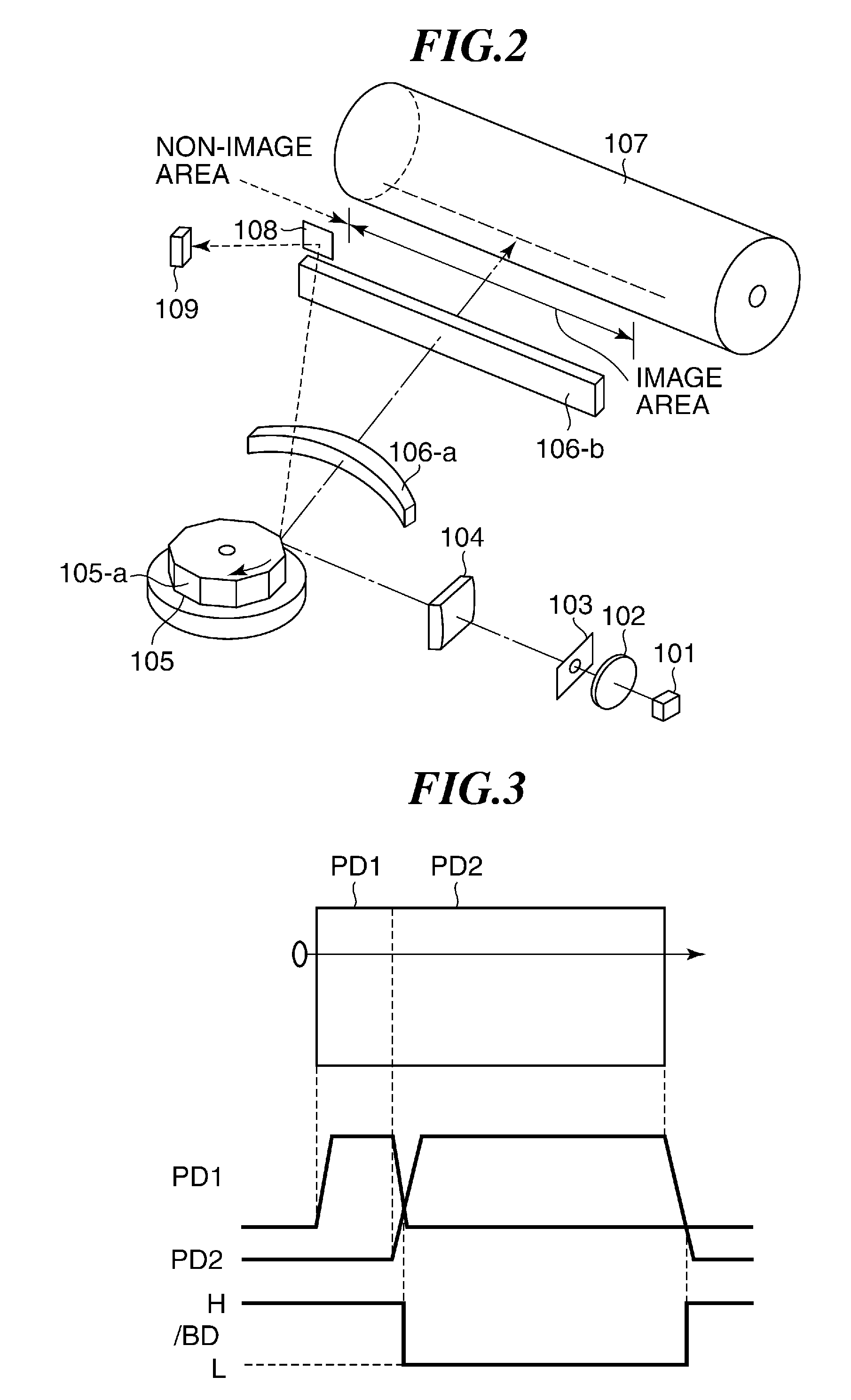
[0026]FIG. 1 is a schematic view of an image forming apparatus using a light beam scanning device according to the present invention.

[0027]The image forming apparatus shown in FIG. 1 forms a color image by superimposing respective images of the colors of cyan (C), magenta (M), yellow (Y), and black (K) one upon another.

[0028]The image forming apparatus, denoted by reference numeral 1A, shown in FIG. 1 has four photosensitive drums 14, 15, 16, and 17 as photosensitive members. An intermediate transfer belt (endless belt) 13 as an intermediate transfer member is disposed in facing relation to the photosensitive drums 14, 15, 16, and 17.

[0029]The intermediate transfer belt 13 is stretched around a driving roller 13a, a secondary transfer opposed roller 13b, and a tension roller (driven roller) 13c such that the general shape of the intermediate transfer belt 13 in cross-sectional view is triangular. The intermediate transfer belt 13 rotates in a clockwise direction as viewed in FIG. 1 ...

second embodiment

[0104]Next, a description will be given of a light beam scanning device according to a

[0105]In the second embodiment, similarly to the first embodiment, scanning light is received by the two-division photodiode sensor 109, whereby the detection of an image writing start position and the automatic power control are performed.

[0106]FIG. 8 is a block diagram of a control system used in the light beam scanning device according to the second embodiment. In the second embodiment, the same components of the control system as those of the control system shown in FIG. 4 are denoted by the same reference numerals, and description thereof is omitted. Further, a CPU and a semiconductor laser drive circuit of the present embodiment are different in function from the CPU 411 and the semiconductor laser drive circuit 413 of the first embodiment, and hence they are denoted by reference numeral 811 and 813, respectively.

[0107]The illustrated control system (also referred to as the light beam scannin...

third embodiment

[0117]In the third embodiment, the light emitting element to be subjected to the automatic power control is switched according to a change in the processing speed caused e.g. by a change in the image mode, and hence it is possible to efficiently perform the automatic power control on all of the laser beams, according to the processing speed.

[0118]Next, a fourth embodiment of the present invention will be described. The fourth embodiment is distinguished from the first to third embodiments described above in processing in which a light emitting element of which the automatic power control has been completed is extinguished (turned off), and a light emitting element to be subjected to the automatic power control next is lit (turned on) to execute the automatic power control, but is similar in the other points of basic configuration, and hence only different points will be described.

[0119]Referring to FIG. 7. when the automatic power control of the light emitting element E1 correspondi...


PUM


Abstract

A light beam scanning device capable of suppressing lowering of accuracy of light amount control when scanning a photosensitive member using light beams. A semiconductor laser has light emitting elements for emitting respective light beams. A polygon mirror deflects the light beams such that each light beam scans a photosensitive member in a predetermined direction. A photodiode sensor is disposed where the light beams enter. A CPU controls the light amount of each light beam based on an output from the sensor. The first and second light emitting elements are arranged such that respective light beams therefrom are adjacent to each other in the direction and there is time during which both the light beams enter the sensor. The CPU executes the control for the first and second light emitting element, at receptive different cycles of scanning of the light beams.

Description

BACKGROUND OF THE INVENTION[0001]1. Field of the Invention[0002]The present invention relates to a light beam scanning device and an image forming apparatus, and more particularly to light amount control performed by an image forming apparatus, such as a laser beam printer, in scanning a photosensitive member using a plurality of light beams.[0003]2. Description of the Related Art[0004]In recent image forming apparatuses provided with a light beam scanning device, with a view to increasing the printing speed and enhancing the resolution of output images, the number of light emitting elements (light emitting points) provided in a light source, such as a semiconductor laser, is increased, whereby an image is formed by simultaneously scanning a photosensitive member using a plurality of light beams.[0005]The image forming apparatuses that scan a photosensitive member using a plurality of light beams are capable of achieving higher printing speed and higher resolution of output images w...

Claims


Application Information

Patent Timeline
Patent Type & Authority Applications(United States)
IPC IPC(8): B41J2/385
CPCB41J2/473
Inventor NITO, YUTA
Owner CANON KK
Why Eureka
Try Eureka