
Apparatus and method for controlling a gas sensor

a technology of gas sensor and apparatus, applied in the direction of process and machine control, instruments, electrochemical variables of materials, etc., can solve the problems of deterioration of accuracy in detecting concentration of specific gas components in the gas to be measured, and achieve the effect of suppressing deterioration of accuracy

Active Publication Date: 2011-07-14
NGK SPARK PLUG CO LTD
View PDF13 Cites 5 Cited by
  • Summary
  • Abstract
  • Description
  • Claims
  • Application Information

AI Technical Summary

Benefits of technology

The present invention relates to a gas sensor control apparatus and method that can prevent deterioration in accuracy when detecting the concentration of specific gas components in a gas to be measured, even when the internal resistance of the gas sensor is rapidly changed due to element cooling or the like. The gas sensor control apparatus includes an internal resistance detection means, concentration detection means, heater current supply control means, determination means, and nullification information generation means. The nullification information is transmitted to the external device to nullify the detected value of the concentration, and the detected value is outputted together with the nullification information. This can help to prevent the deterioration in accuracy in detecting the concentration of specific gas components in the gas to be measured.

Problems solved by technology

Further, if the internal resistance value of the cell is temporally largely changed due to the element cooling or the rapid temperature rise, the detection value of the gas concentration (the NOx concentration or the like) will be changed to thereby cause deterioration of accuracy in detecting concentration of specific gas components in the gas to be measured.

Method used


Image

  • Apparatus and method for controlling a gas sensor
  • Apparatus and method for controlling a gas sensor
  • Apparatus and method for controlling a gas sensor

Examples


Embodiment Construction

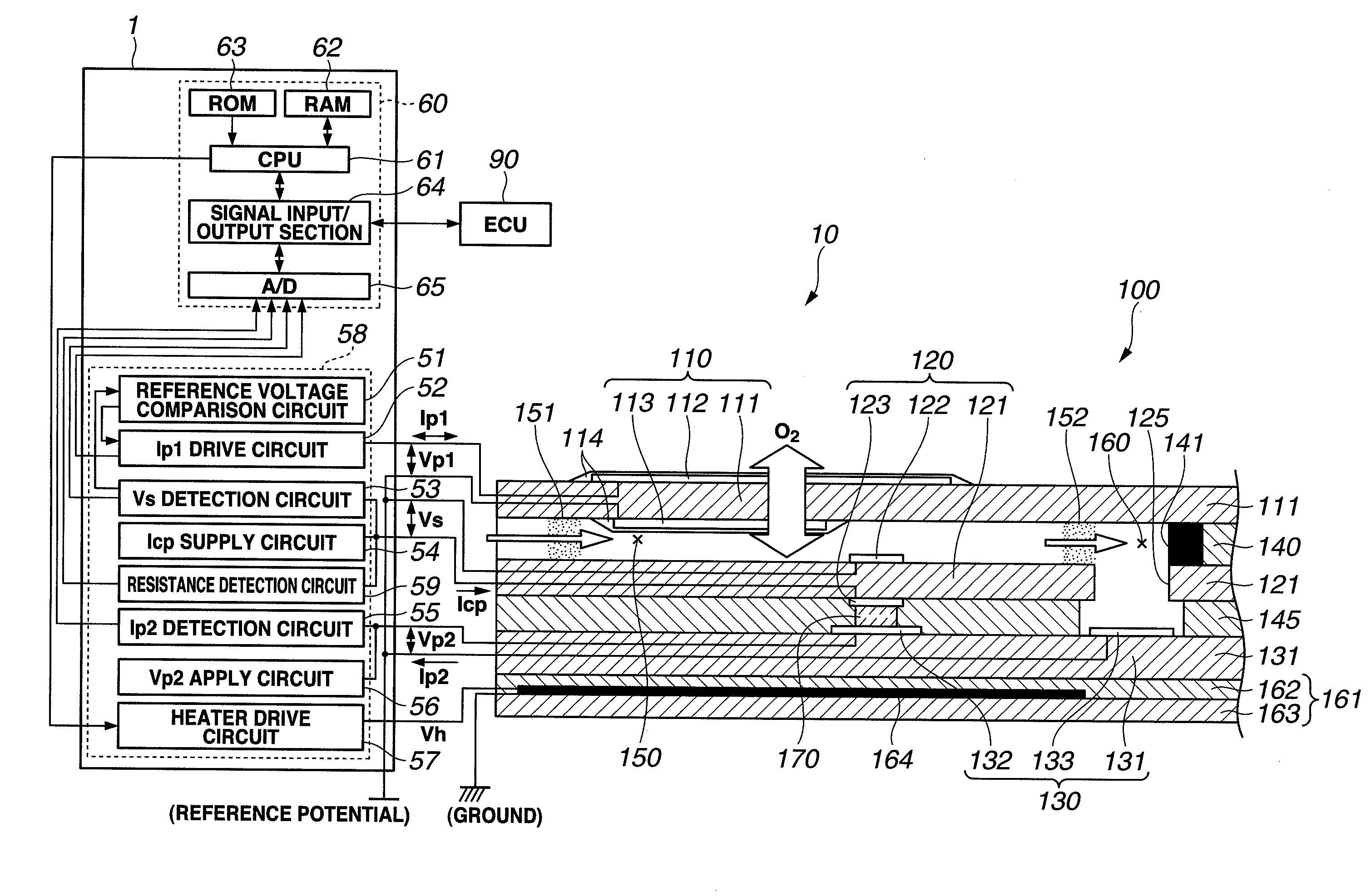
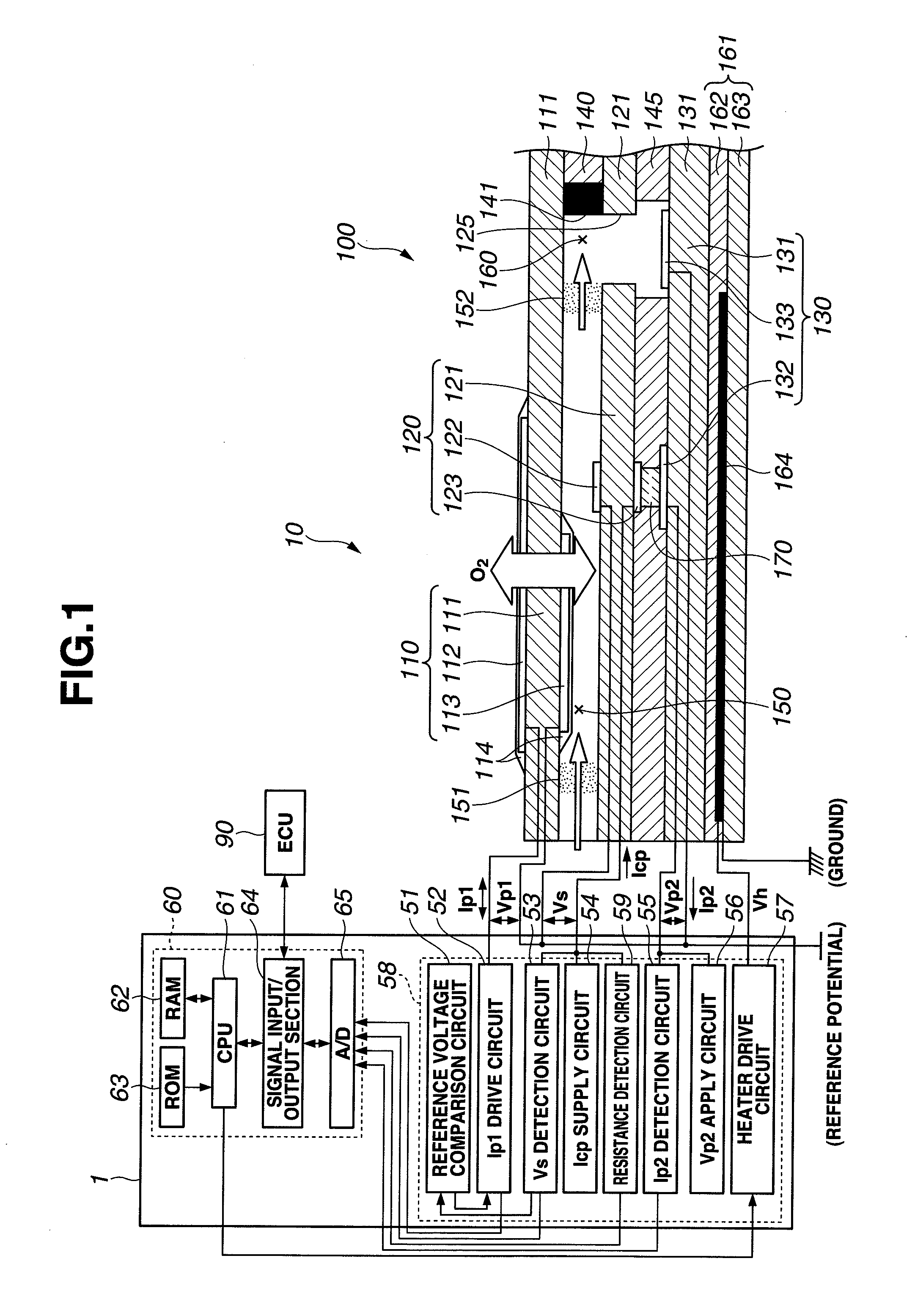
[0039]In the following, an embodiment of the present invention is explained by referring to the accompanying drawings. FIG. 1 shows a block diagram of a gas sensor control apparatus (controller) 1 according to the embodiment and a structural diagram of a gas sensor 10 connected to the gas sensor control apparatus. The gas sensor control apparatus 1 is installed onto a vehicle equipped with an internal combustion engine (hereinafter also referred to as an engine), not shown. The gas sensor control apparatus 1 is electrically connected to not only a connector (not shown) of the gas sensor (NOx sensor) 10 but also a vehicle-side control apparatus (ECU 90) via a harness. In this embodiment, the gas sensor 10 is a NOx sensor and the gas sensor control apparatus 1 serves as a NOx sensor control apparatus. Therefore, the gas sensor 10 is hereinafter also referred to as the NOx sensor 10 and the gas sensor control apparatus 1 is hereinafter also referred to as the NOx sensor control apparat...


PUM

PropertyMeasurementUnit
voltageaaaaaaaaaa
constant voltageaaaaaaaaaa
internal resistance valueaaaaaaaaaa

Abstract

A gas sensor control apparatus including internal resistance detection means for detecting an internal resistance value of one of cells of a gas sensor, concentration detection means for detecting a concentration value of a specific gas component in a gas to be measured and outputting the detected concentration value, heater current supply control means for controlling a current to be supplied to a heater of the gas sensor such that the detected internal resistance value becomes a target value, determination means for determining whether or not the detected internal resistance value is within a permissible range including the target value, nullification information generation means for generating nullification information to nullify the detected concentration value, when it is determined that the target value is out of the permissible range, and nullification information output means for outputting the nullification information to an external device connected to the gas sensor control apparatus.

Description

BACKGROUND OF THE INVENTION[0001]The present invention relates to a gas sensor control apparatus adapted for connecting to a gas sensor which includes at least one cell having a solid electrolyte layer and a pair of electrodes, and a heater, detecting a concentration of a specific gas component in a gas to be measured via the gas sensor, outputting the concentration detected to an outside thereof and controlling supply of an electric current to the heater, and relates to a method for controlling the gas sensor.[0002]An oxygen sensor and an air-fuel ratio sensor are known as a gas sensor which is used for enhancing fuel economy and controlling combustion in an internal combustion engine for a vehicle such as an automobile. In addition, with enforcement of strict automobile emission control, there is a demand for reduction of nitrogen oxide (NOx) in exhaust gas. To meet the demand, a NOx sensor capable of directly detecting a NOx concentration has been proposed.[0003]As such a gas sen...

Claims


Application Information

Patent Timeline
Patent Type & Authority Applications(United States)
IPC IPC(8): G01N27/407
CPCG01N27/419G01N27/4071
Inventor SASAKI, HISASHI
Owner NGK SPARK PLUG CO LTD
Learn More