
Colored smart card module

a smart card module and module technology, applied in the field of colored smart card modules, can solve the problems of increasing the risk of connection failure, difficult to provide an integrated circuit connection element on the substrate, and reducing the aesthetic appeal of the overall smart card, so as to achieve accurate positioning and maintain the adhesion properties of metallic conductors

Active Publication Date: 2017-04-11
PARLEX PACIFIC LTD
View PDF8 Cites 10 Cited by
  • Summary
  • Abstract
  • Description
  • Claims
  • Application Information

AI Technical Summary

Benefits of technology

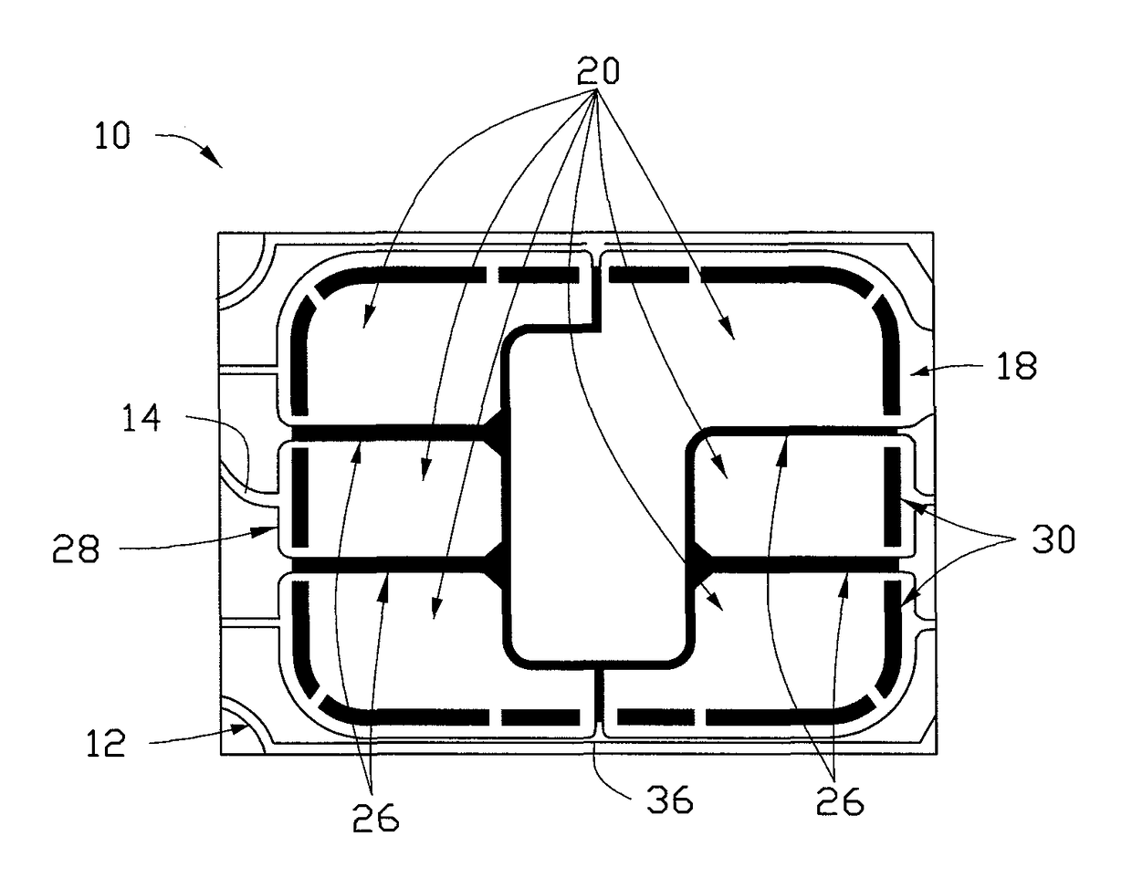
[0016]Traditionally, the voids between the contact pads have been merely functional, providing electrical separation between adjacent contact pads. The advantage of the present invention is that these voids can now be used to enhance the visual appeal of the whole smart card.
[0017]Additionally or alternatively, the said optical access from the first side may be provided about a perimeter of the card-reader contact element.
[0018]The most obviously distracting part of many existing smart cards is the perimeter around the card-reader contact element; in order to accommodate any tolerance in the system, the aperture for the card-reader contact element in the smart card body is in fact slightly larger than the card-reader contact element, meaning that at least a portion of the perimeter of substrate will be visible. In the present invention, this portion can be disguised within the overall aesthetic appearance of the smart card.
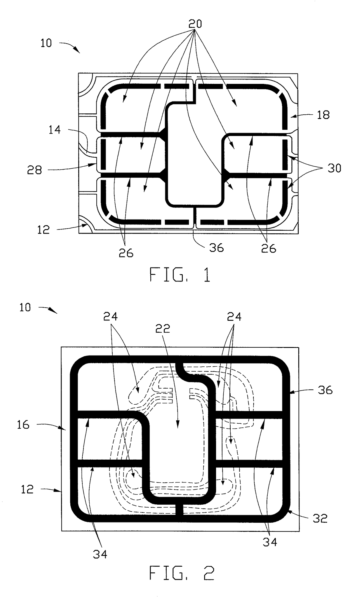
[0019]Furthermore, the card-reader contact element may include at least one locator void, said optical access from the first side is provided through the at least one locator void.
[0020]By providing a locator void permitting optical access through the substrate within an area of the card-reader contact element, an integrated circuit chip attached to the second side of the substrate can be accurately positioned within the smart card body. Furthermore, such locator voids may be able to provide an additional and / or alternative means of providing a visual appeal of the smart card.
[0021]The substrate may preferably comprise polyethylene terephthalate, and the substrate may be a flexible substrate, transparent, and / or translucent.

Problems solved by technology

Regardless of how the colored smart card module is installed into the smart card, at least a portion of the substrate will be visible to a user, and the coloration of the substrate can diminish the aesthetic appeal of the overall smart card.
This dye impacts the adhesion of electrically conductive material to the surface of the substrate, making it difficult to provide an integrated circuit connection element on the substrate, substantially increasing the risk of connection failure.
The application of this dye is also relatively expensive, increasing the cost-per-unit to manufacture a smart card module by a significant percentage.
Different dye colors can be utilized, but, due to the small numbers typically required, are not due to the extensive testing required to make sure robustness is maintained over the life of the module.

Method used


Image

  • Colored smart card module
  • Colored smart card module
  • Colored smart card module

Examples


Embodiment Construction

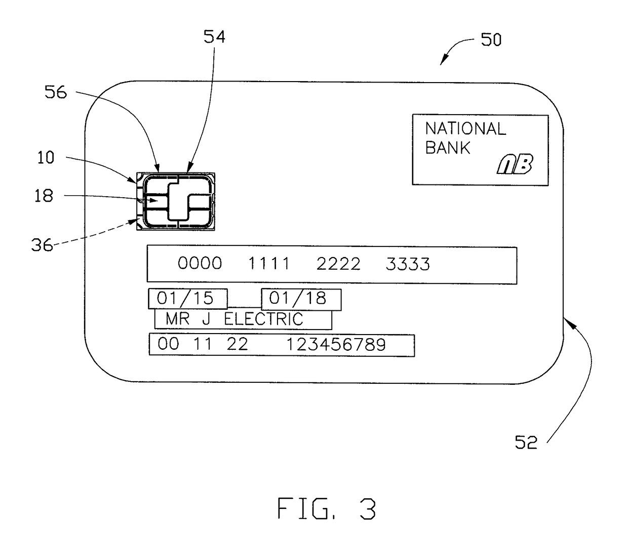
[0031]Referring firstly to FIGS. 1 and 2, there is illustrated a colored smart card module, indicated globally at 10, for use as part of a smart card, such as a bank card.

[0032]The colored smart card module 10 comprises a substrate 12 having a first side 14, shown in FIG. 1, and a second side 16, shown in FIG. 2, which is on the opposite side of the substrate 12 to the first side 14.

[0033]The substrate 12 used here is a light-transmissible, preferably transparent or substantially transparent, polyethylene terephthalate (PET) onto which metal plating may be readily applied to form the necessary electrically conductive layers of the module 10. PET is the industry-standard material in this respect, but any appropriately robust and light-transmissible substrate may be utilized, such as a transparent epoxy glass. The substrate 12 is therefore generally a flexible substrate, but could be provided as a rigid substrate if desired.

[0034]On the first side 14 of the substrate 12 is formed a ca...


PUM


Abstract

A colored smart card module having a light-transmissible substrate with first and second sides; a card-reader contact element formed on the first side of the substrate; and a colored ink layer printed on the second side of the substrate. The printed colored ink layer is then at least in part visible from the first side of the substrate around the card-reader contact element. A smart card including such a colored smart card module is also provided.

Description

CROSS REFERENCE TO RELATED APPLICATIONS[0001]This non-provisional patent application claims priority under 35 U.S.C. §119(a) from Patent Application No. 1510252.8 filed in United Kingdom on Jun. 12, 2015, the entire contents of which are hereby incorporated by reference.FIELD OF THE INVENTION[0002]This invention relates to a colored smart card module for a smart card, and to a smart card utilizing such a colored smart card module.BACKGROUND OF THE INVENTION[0003]Smart cards are widely used for a variety of applications, and in particular are used as bank cards, such as credit or debit cards, to authorize financial transactions for a user. Such cards are often colored over the entire smart card body aside from contacts, either for aesthetic appeal, to reflect branding of the card-issuing company, or a combination thereof.[0004]To provide a physical card-reader contact for the smart card, a separate module is constructed and then inserted into the smart card body during assembly. Such...

Claims


Application Information

Patent Timeline
Patent Type & Authority Patents(United States)
IPC IPC(8): G06K19/077G06K19/04G06K19/02
CPCG06K19/07747G06K19/02G06K19/044G06K19/0772
Inventor WARD, DOMINIC JOHN
Owner PARLEX PACIFIC LTD
Learn More