Imaging apparatus to control rotation of an image capturing device

a technology of imaging apparatus and rotational control, which is applied in the field of imaging apparatus, can solve the problems of image indistinctness and failure of imaging apparatus, and achieve the effect of reducing vibration and lowering acceleration

Active Publication Date: 2017-04-11
CANON KK
View PDF6 Cites 2 Cited by
  • Summary
  • Abstract
  • Description
  • Claims
  • Application Information

AI Technical Summary

Problems solved by technology

Thus, when control of the acceleration sets a condition of generating the vibration, an image may be indistinct due to vibration or the like of the image capturing unit.
Further, the vibration may cause a failure of the imaging apparatus.

Method used


Image

  • Imaging apparatus to control rotation of an image capturing device
  • Imaging apparatus to control rotation of an image capturing device
  • Imaging apparatus to control rotation of an image capturing device

Examples


Embodiment Construction

[0025]Hereinafter, exemplary embodiments of the present invention will be described in detail. Configurations of the exemplary embodiments are only examples, and are in no way limitative of the present invention.

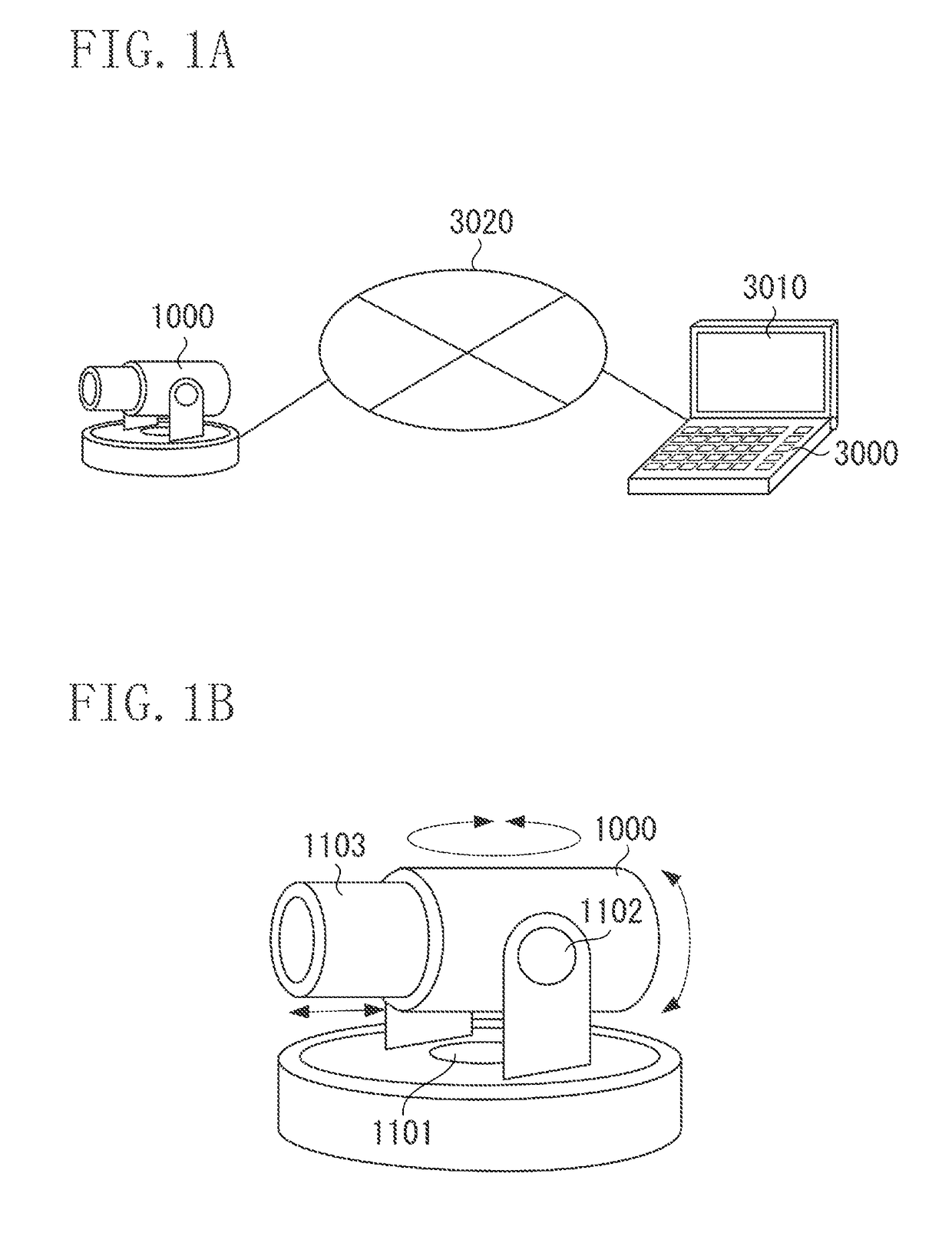
[0026]FIG. 1A is a diagram illustrating an example of a configuration of an imaging system according to a first exemplary embodiment. In the imaging system according to the present exemplary embodiment, an imaging apparatus 1000 is connected to a client 3000 via a network 3020. This enables the imaging apparatus 1000 to communicate with the client 3000. The imaging apparatus 1000 transmits a captured image to the client 3000 via the network 3020.

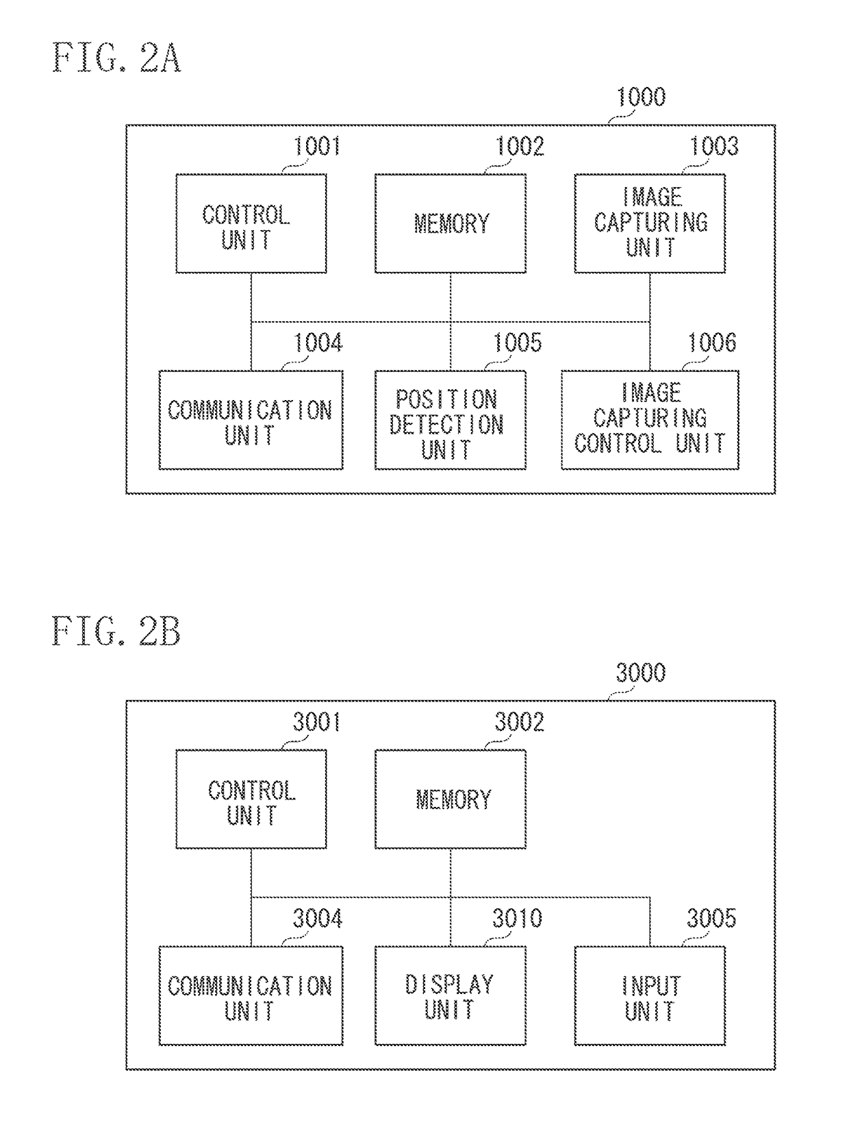
[0027]The client 3000 is an example of an external apparatus. A display unit 3010 will be described below referring to FIG. 2B. The imaging apparatus 1000 according to the present exemplary embodiment is a monitoring camera for capturing a moving image, and more specifically a network camera used for monitoring. The imaging apparatus...


PUM


Abstract

An imaging apparatus to communicate with an external apparatus via a network includes an image capturing unit, a rotation unit, a reception unit, first and second control units, a determination unit, and a control switching unit. The rotation unit rotates the image capturing unit in a predetermined direction. The reception unit receives a control command including information for designating acceleration when the rotation unit rotates the image capturing unit. The first control unit controls the rotation unit at the designated acceleration. The second control unit controls the rotation unit at acceleration that is different from the designated acceleration. The determination unit determines whether a speed at which the rotation unit rotates the image capturing unit is within a predetermined range. The control switching unit switches between the first control unit and the second control unit according to a determination result of the determination unit, and control the rotation unit.

Description

BACKGROUND OF THE INVENTION[0001]Field of the Invention[0002]The present invention relates to an imaging apparatus. For example, the present invention relates to an imaging apparatus capable of rotating an image capturing unit configured to capture an image of a subject in a predetermined direction.[0003]Description of the Related Art[0004]There has been known an imaging apparatus that can change a direction for capturing an image of a subject by moving a pan head.[0005]Further, there has been known an imaging apparatus that can change a direction for capturing an image according to an instruction transmitted from an external apparatus connected to the imaging apparatus via a network.[0006]Japanese Patent Application Laid-Open No. 2003-8973 discusses an imaging apparatus capable of changing a direction for capturing an image by moving a pan head through a key operation of a mobile phone having a browser function or a mouse operation of a personal computer.[0007]Use of such an imagin...

Claims


Application Information

Patent Timeline
Patent Type & Authority Patents(United States)
IPC IPC(8): H04N5/232H04N7/18
CPCH04N5/23238H04N5/232H04N7/18H04N7/183H04N23/661H04N23/695H04N23/698
Inventor HAGA, MINORU
Owner CANON KK
Why Eureka
Try Eureka