
Printhead and fluid interconnection

a technology of fluid interconnection and printhead, applied in printing and other directions, can solve the problems of reduced printing accuracy, uncustomisable existing external fluid delivery system, and reduced printing accuracy, and achieve the effect of improving convenience and customization

Active Publication Date: 2017-04-18
FUNAI ELECTRIC CO LTD
View PDF15 Cites 1 Cited by
  • Summary
  • Abstract
  • Description
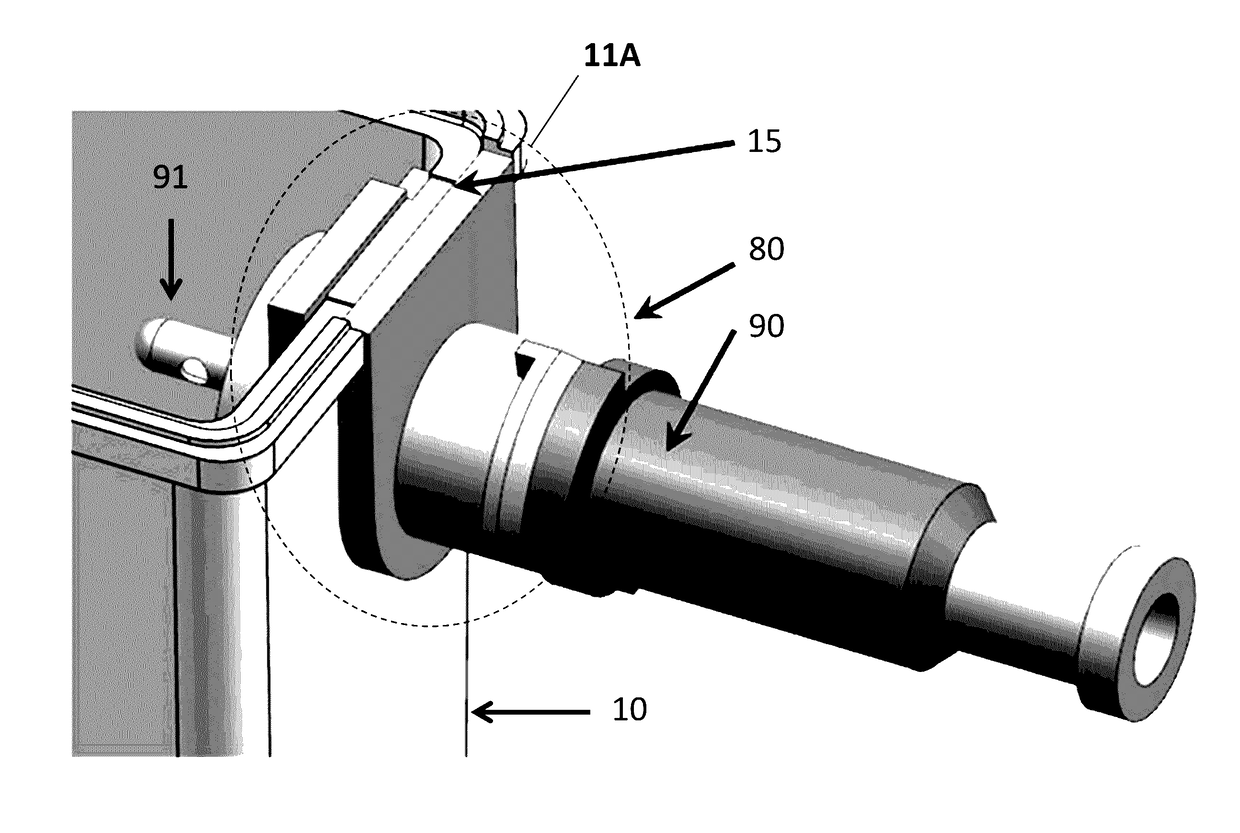
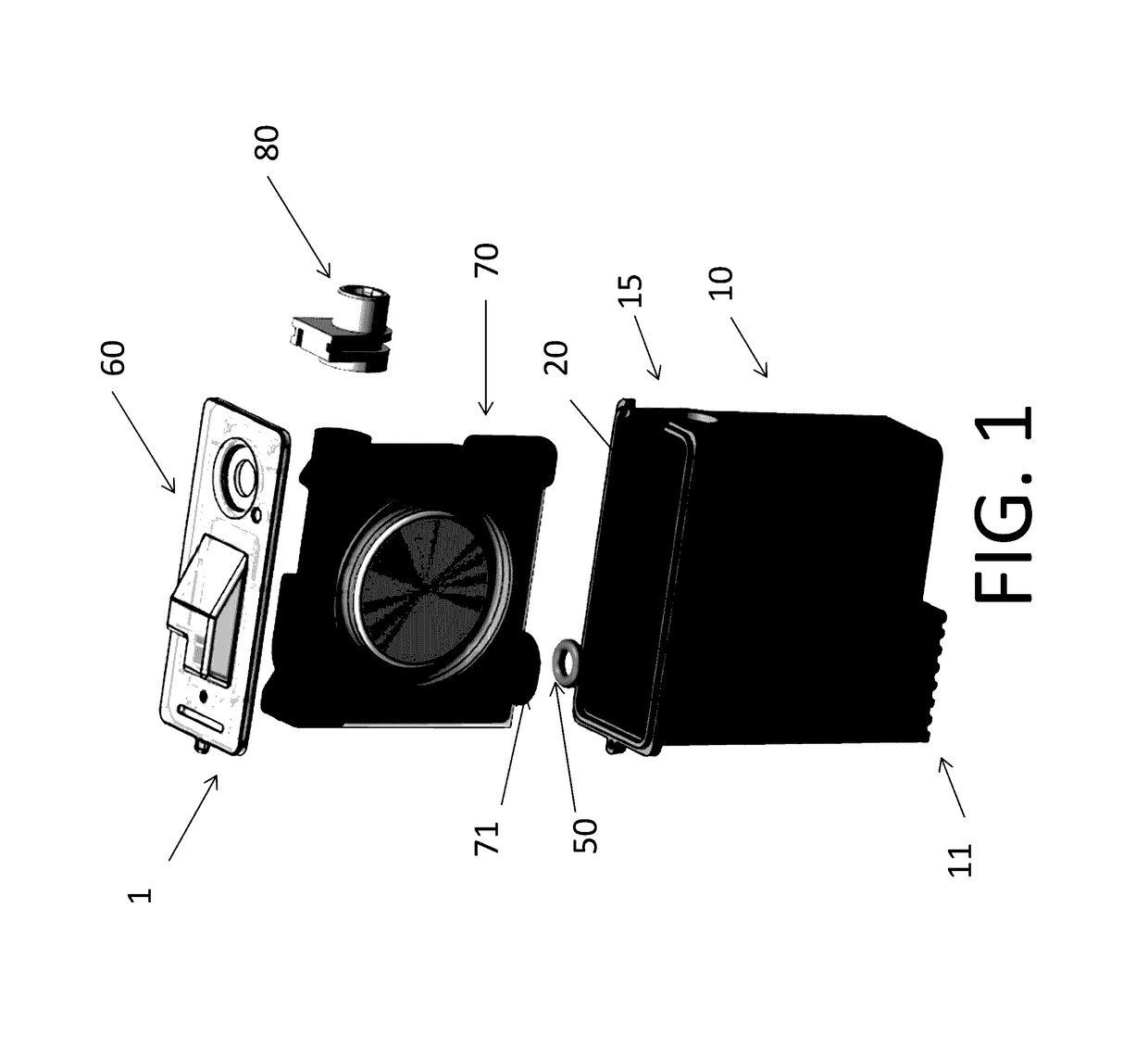
  • Claims
  • Application Information

AI Technical Summary

Benefits of technology

[0008]An object of this invention is to provide a print cartridge with a fluid interconnecting mating feature that allows the print cartridge to connect to an external fluid delivery system with improved convenience and customization.
[0009]The print cartridge is designed to accept a guided mating component. The mating component is designed to connect to the print cartridge later in the assembly process for reduced manufacturing complexity and increased convenience and customization capabilities. A fluid interconnector connects at one end to the mating component and at the other end to the external fluid supply. Fluid such as ink is transferred from the external ink supply through the fluid interconnector and mating component and into the print cartridge.
[0010]The mating component is designed to be robust and interlock with parts on the print cartridge for easy alignment with the external fluid supply, a secure connection, and easy connect-disconnect options for the user. The mating component can be interchanged with other like-systems, which allows the printing system to remain versatile and fit the user's needs for different types of printing tasks. The mating component can be interchanged depending on the external fluid's viscosity, or if the user desires a different fluid flow, to name a few. Further, a removable mating component also allows the user to easily diagnose blockages, air accumulation, and leakages in the ink delivery system.

Problems solved by technology

More expensive, business grade printers use progressively larger ink tanks on the printhead, but as the print swath width and / or height, and / or the speed at which the printhead moves increases, it eventually becomes impractical to have the tanks integrated with the printheads due to the high mass and inertia the liquid volume adds to the printheads, which results in reduced printing accuracy.
Further, with ink tanks located on the printhead, replacement typically requires repriming and alignment checks that necessarily require aborting any current job.
However, external fluid delivery systems have several drawbacks.
Existing external fluid delivery systems are not customizable; printhead assemblies in these systems are typically sold with ink and are designed to be used only for that system.
Thus, existing systems lack versatility for multiple purpose use.
Other drawbacks of existing external fluid delivery systems include: undesirable fluctuations in ink pressure in the print cartridge, an unreliable and complex fluid seal between the print cartridge and the external ink supply, a difficult fluid connection alignment process from the print cartridge to the external ink supply, increased printer size due to the external ink supply's connection to the print cartridge, blockage in the ink delivery system, air accumulation in the tubes leading to the print cartridge, leakage of ink, high cost, and complexity.
A further disadvantage is that current external fluid delivery systems, specifically printhead assemblies, require complex assembly and manufacturing processes.
These parts may have a large footprint on the assembly line, which typically requires additional tooling and cost to complete the manufacturing process.

Method used


Image

  • Printhead and fluid interconnection
  • Printhead and fluid interconnection
  • Printhead and fluid interconnection

Examples


Embodiment Construction

[0048]In exemplary embodiments of the present invention, a fluid interconnection with a guided mating component is provided that allows a print cartridge to connect to an external fluid delivery system. The fluid interconnection allows for reduced manufacturing complexity and customization.

[0049]The headings used herein are for organizational purposes only and are not meant to be used to limit the scope of the description or the claims. As used throughout this application, the words “may” and “can” are used in a permissive sense (i.e., meaning having the potential to), rather than the mandatory sense (i.e., meaning must). Similarly, the words “include,”“including,” and “includes” mean including but not limited to. To facilitate understanding, like reference numerals have been used, where possible, to designate like elements common to the figures.

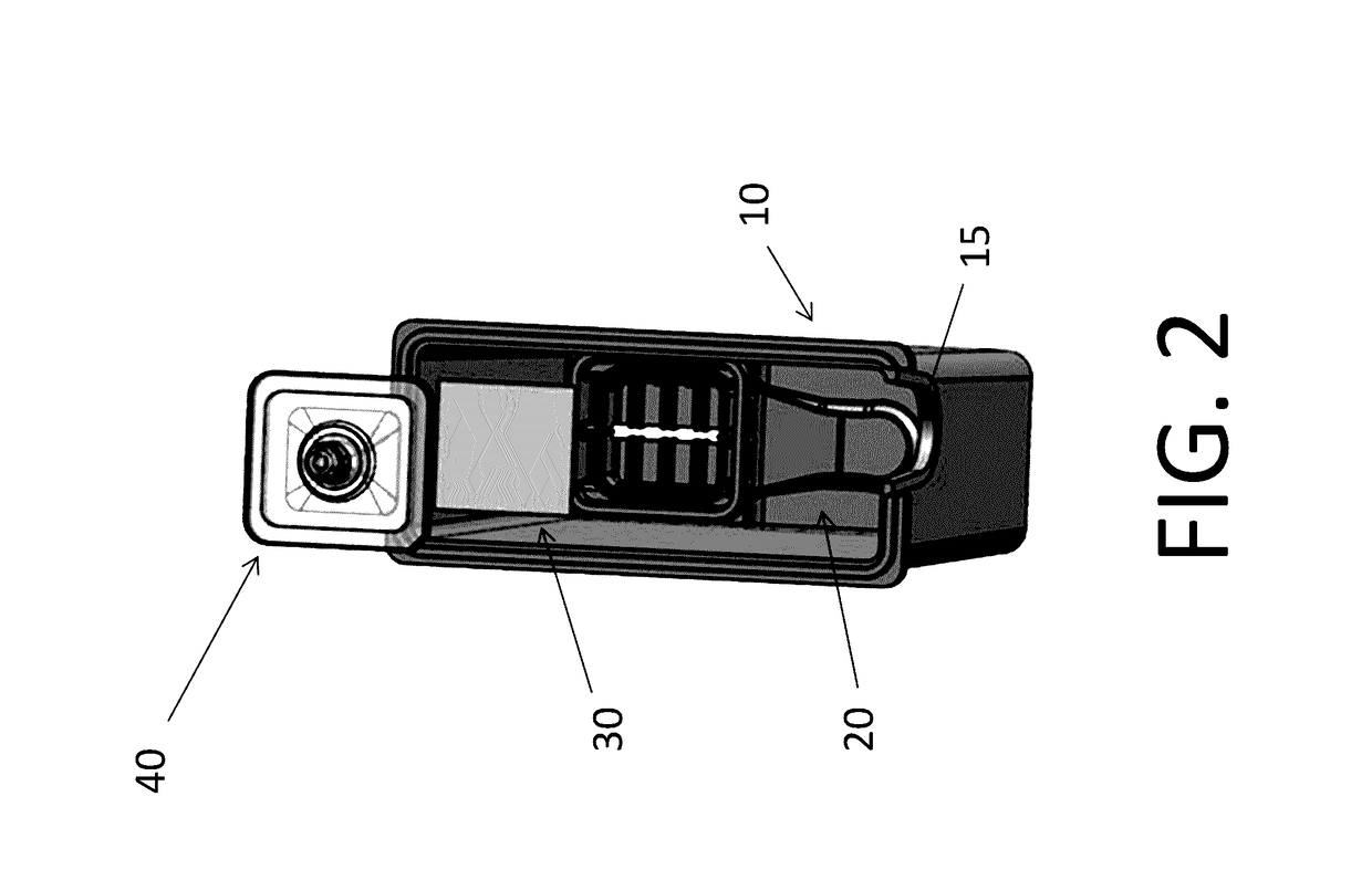
[0050]Initially referring to FIG. 1 and FIG. 2, a print cartridge according to an exemplary embodiment of the present invention includes a ...


PUM


Abstract

A fluid interconnect system including a mating component having an inlet port and a liquid outlet, the inlet port configured to support an interconnector and the liquid outlet configured to engage with a print cartridge so that liquid flows from a liquid source, through the interconnector and the inlet port, and out of the liquid outlet into the print cartridge.

Description

FIELD OF THE INVENTION[0001]The present invention generally relates to inkjet printers, and more particularly, to a fluid interconnecting mating feature between a print cartridge and an external fluid supply.BACKGROUND OF THE INVENTION[0002]Conventional ink jet printers include a printhead and a carrier. The ink jet printhead may comprise a printhead body, nozzles, and corresponding ink ejection actuators. The actuators cause ink to be ejected from the nozzles onto a print medium at selected ink dot locations within an image area. The carrier moves the printhead relative to the medium, while the ink dots are jetted onto selected pixel locations.[0003]A common type of inkjet printer uses a replaceable print cartridge which may contain a printhead and a supply of ink contained within the print cartridge. The print cartridge is not intended to be refillable and when the initial supply of ink is depleted, the print cartridge is discarded and a new print cartridge is installed within the...

Claims


Application Information

Patent Timeline
Patent Type & Authority Patents(United States)
IPC IPC(8): B41J2/175
CPCB41J2/17523B41J2/175B41J2/17509B41J2/17513B41J2/17553B41J2/17556B41J2/17506
Inventor KOMPLIN, STEVEN R.
Owner FUNAI ELECTRIC CO LTD
Learn More