
Airbag apparatus

a technology of airbags and airbags, which is applied in the direction of pedestrian/occupant safety arrangements, vehicular safety arrangments, vehicle components, etc., can solve the problems of over-regulating (suppression) the deployment and inflation of airbags, and achieve the effect of preventing airbags from strongly interfering with the windshield

Active Publication Date: 2017-04-18
TOYODA GOSEI CO LTD
View PDF18 Cites 7 Cited by
  • Summary
  • Abstract
  • Description
  • Claims
  • Application Information

AI Technical Summary

Benefits of technology

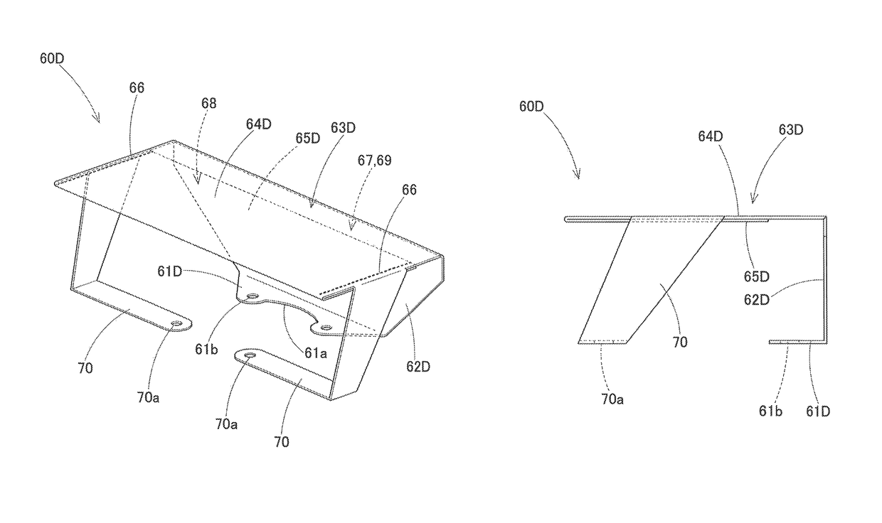
[0007]However, in the airbag apparatus of the related art, the box-shaped holding member has shape holding properties so as to maintain the folded shape of the airbag. When the folded portion of the airbag is released, a cylindrical opening at an end of the holding portion of the holding member (regulating member) is widened. In the airbag apparatus of the related art, a circumferential wall of the holding portion is fixed to a rigid attachment portion of the airbag apparatus. For this reason, the circumferential edge of the opening of the holding portion is unlikely to be deformed, and the folded portion can be smoothly released. That is, in the airbag apparatus of the related art, there is a problem in excessively regulating (suppressing) the deployment and inflation of the airbag.
[0008]The present invention is made to solve the problem, and an object of the present invention is to provide an airbag apparatus that smoothly regulates the deployment and inflation of an airbag and releases the regulation at an initial stage of the deployment and inflation.

Problems solved by technology

That is, in the airbag apparatus of the related art, there is a problem in excessively regulating (suppressing) the deployment and inflation of the airbag.

Method used


Image

  • Airbag apparatus
  • Airbag apparatus
  • Airbag apparatus

Examples


Embodiment Construction

[0087]Preferred embodiments of the present invention are described below with reference to accompanying drawings. However, the invention is not regulated to the embodiments disclosed herein. All modifications within the appended claims and equivalents relative thereto are intended to be encompassed in the scope of the claims.

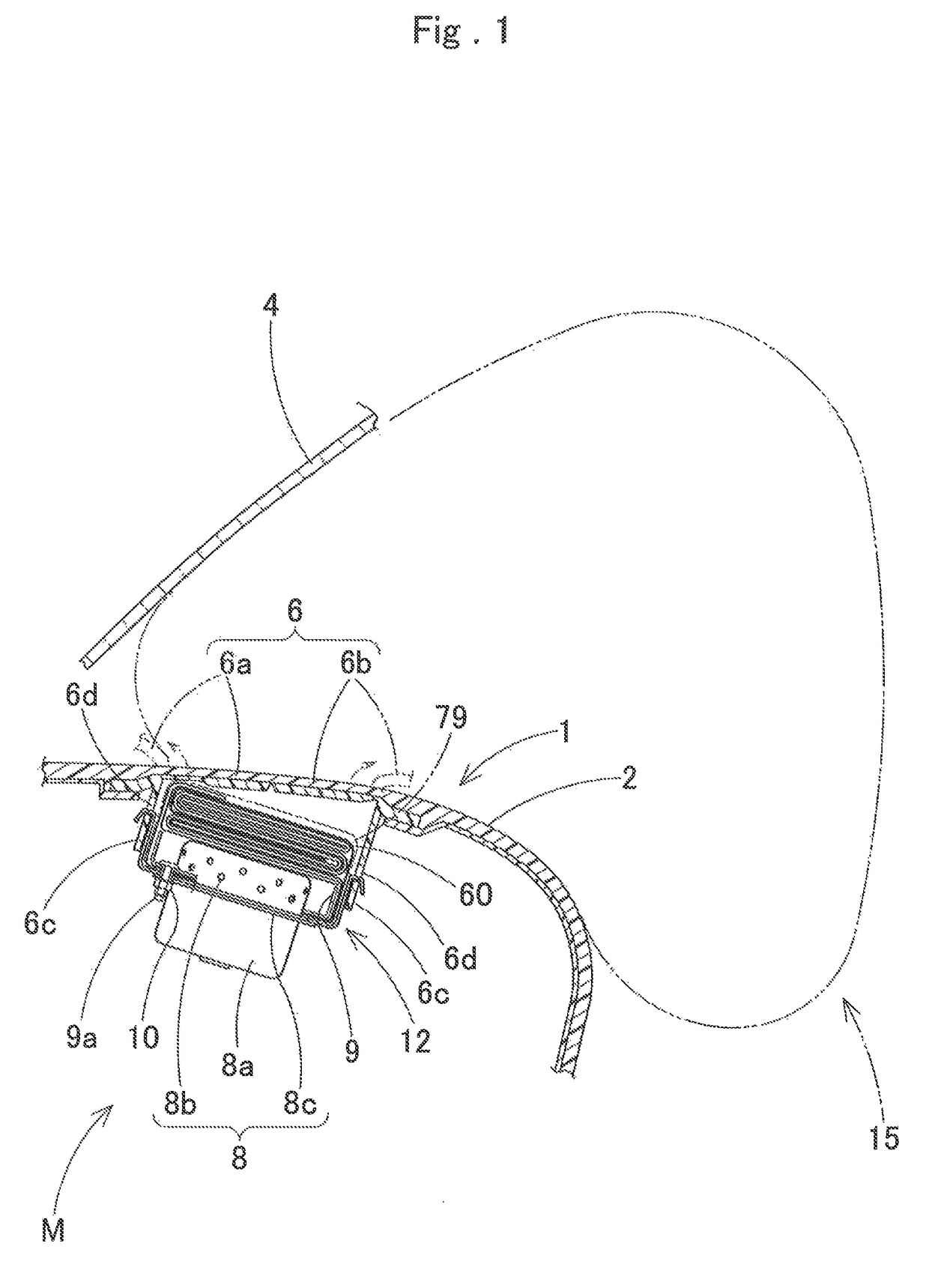
[0088]In an embodiment, a front passenger seat airbag apparatus M that is disposed in front of a front passenger seat will be described as an example of an airbag apparatus. As illustrated in FIG. 1, the front passenger seat airbag apparatus M (hereinafter, referred to as an “airbag apparatus”) of the embodiment is a top mounted airbag apparatus, and is mounted inside an instrument panel 1 below a windshield 4 so as to be positioned below an upper surface 2 of the instrument panel 1.

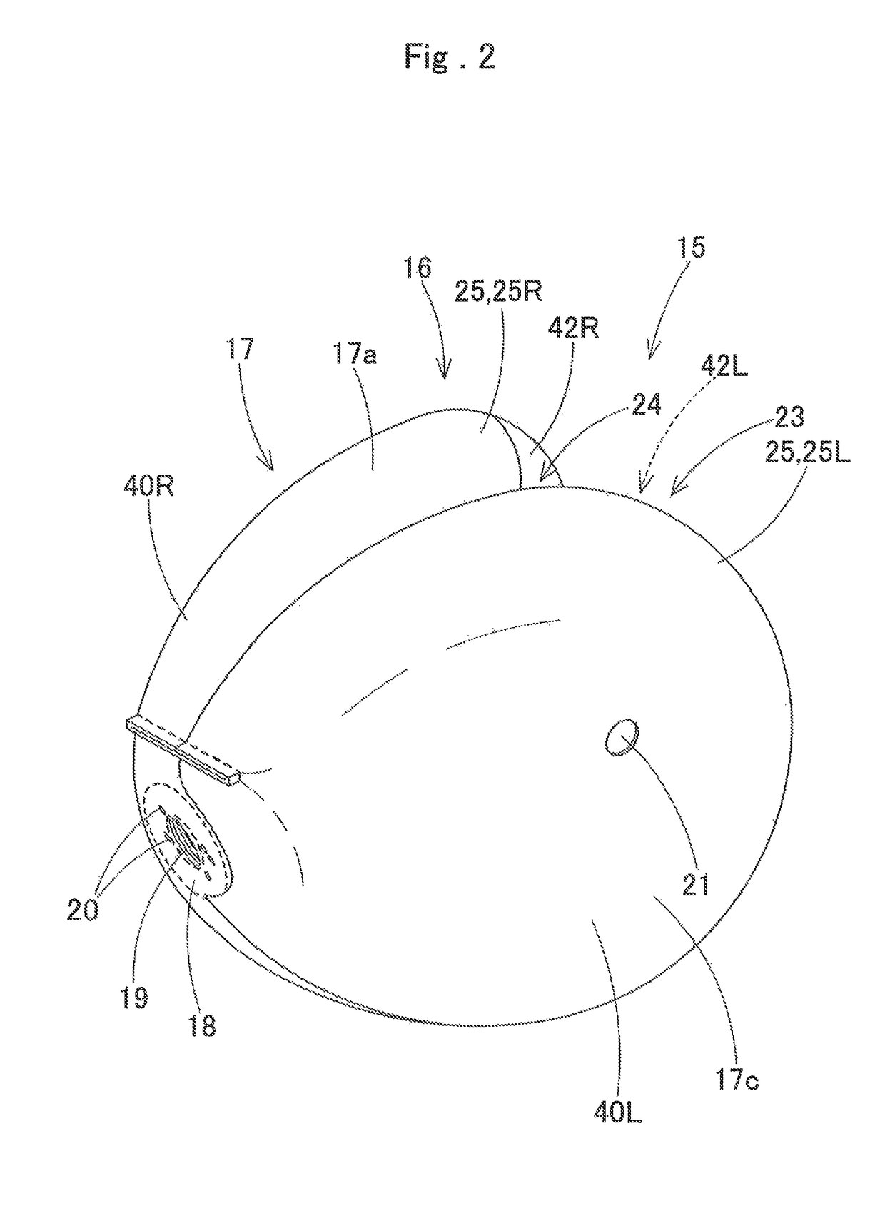
[0089]As illustrated in FIGS. 1 and 12, the airbag apparatus M includes a folded airbag 15; an inflator 8; a case 12; a retainer 9; and an airbag cover 6. The inflator 8 supplies inf...


PUM


Abstract

An airbag apparatus includes an airbag that deploys and inflates while being unfolded from an accommodating portion, when inflating gas flows into the airbag; and a regulating member that is able to regulate the deployment and inflation of an airbag. The regulating member is flexible, and includes a temporary holding portion that releasably and temporarily holds a folded portion that is a part of the airbag; an attachment portion that is attached to the accommodating portion; and a connecting piece portion that connects the attachment portion and the temporary holding portion. The temporary holding portion includes a base portion that is continuous with the connecting piece portion, and a cover portion that forms a holding concave portion for temporarily holding the folded portion, and is connected to the base portion. An opening for releasing the folded portion is provided at an inner circumference of a non-connected release edge.

Description

[0001]The present application claims priority from Japanese Patent Application No. 2013-227304 of Miura et al., filed on Oct. 31, 2013, Japanese Patent Application No 2014-133012 of Miura et al., filed on Jun. 27, 2014, and Japanese Patent Application No. 2014-173233 of Miura et at, filed on Aug. 27, 2014, the disclosures of which are hereby incorporated into the present application by reference.BACKGROUND OF THE INVENTION[0002]Field of the Invention[0003]The present invention relates to an airbag apparatus mounted in a vehicle, in particular to an airbag apparatus including a regulating member that regulates the deployment and inflation of a part of an airbag when the airbag deploys and inflates.[0004]Description of Related Art[0005]The related art discloses an airbag apparatus that regulates (suppresses) the deployment and inflation of a part of an airbag. When the airbag deploys and inflates, the deployment and inflation of a part of the airbag is suppressed further than other po...

Claims


Application Information

Patent Timeline
Patent Type & Authority Patents(United States)
IPC IPC(8): B60R21/2334B60R21/237B60R21/201B60R21/16
CPCB60R21/2334B60R21/201B60R21/237B60R2021/161
Inventor MIURA, WATARUSHIGEMURA, TAKASHIFURUNO, TSUYOSHI
Owner TOYODA GOSEI CO LTD
Learn More