Flame detecting system

a detection system and flame technology, applied in the field of flame detection systems, can solve the problems of time-consuming integration and difficulty in rapid detection of the presence or absence of flames

Active Publication Date: 2017-04-18
YAMATAKE HONEYWELL CO LTD
View PDF5 Cites 1 Cited by
  • Summary
  • Abstract
  • Description
  • Claims
  • Application Information

AI Technical Summary

Benefits of technology

[0013]According to the present invention, a quantity of received light can be obtained with computation by a digital calculation using a known parameter group stored in advance, an actual operating quantity and a measurement amount and thus, an effect that the presence or absence of a flame can be determined easily and rapidly is obtained.

Problems solved by technology

However, in the method, since electric current flowing between the electrodes is integrated, time for integration is required even when extinguishing the flame.
As a result, it is difficult to rapidly perform detection of the presence or absence of the flame.

Method used


Image

  • Flame detecting system
  • Flame detecting system
  • Flame detecting system

Examples


example 1

[0047]Description will be made on the flow of FIG. 3 (step in the figure is denoted by Snn).

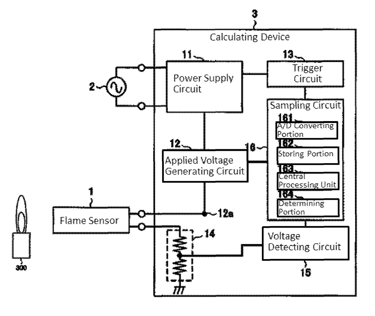
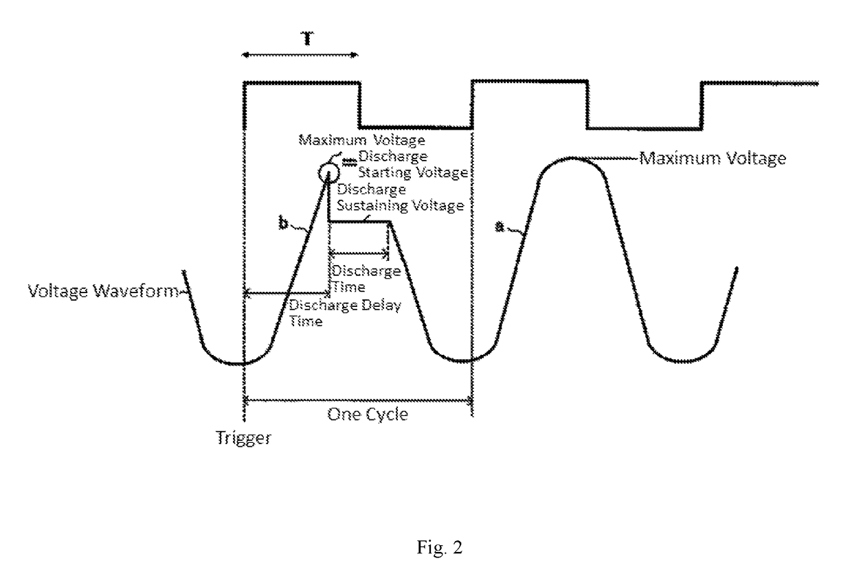
[0048]The operations of the central processing unit 163 are formed of steps for driving the flame sensor 1 with a pulse voltage and calculating the quantity of received light for the flame from a driven result of the flame sensor 1.[0049]A predetermined trigger is received and the flow is started (S00).[0050]The flame sensor is driven to operate the applied voltage generating circuit 12 to apply the voltage greater than or equal to the discharge starting voltage to the flame sensor 1 using a rectangular pulse T having a certain width (S01).[0051]The number of discharge times of the flame sensor 1 caused by repeatedly applying the pulse T to the flame sensor 1 for a predetermined number of times is counted by the signal obtained through the voltage detecting circuit 15 (S02).[0052]The discharge probability P is calculated from the number of discharge times and the number of applied pulses (S03...

example 2

[0060]It is assumed that the pulse width T and the discharge probability P are known in the condition A in Equation 8 described above. For a certain quantity of received light, the flame sensor 1 is activated for plural times using the pulse width T and the discharge probability P is obtained. In this case, it is assumed that a discharge probability is intended to be adjusted to an arbitrary value PC when the next pulse is applied (this is assumed as condition C). Then, a relationship between the condition A and the condition C is expressed as Equation 11. However, it is assumed that the quantity of received light Q is not changed. Equation 12 may also be obtained by performing transformation.

[0061]QB⁢TCQA⁢TA=log(1-PA)⁡(1-PC)[Equation⁢⁢11]T⁢⁢c=TA⁢log(1-PA)⁡(1-PC)[Equation⁢⁢12]

[0062]A pulse width Tc to be set in the condition C can be calculated from Equation 12. The discharge probability can be adjusted to the arbitrary (optimum) value PC in the next plurality of pulses TC. With thi...


PUM


Abstract

To easily obtain a quantity of received light with computation by only measuring pulses of an electric signal related to a flame sensor, a flame detecting system is disclosed comprising: a flame sensor to detect light and a calculating device, in which the calculating device includes an applied voltage generating portion configured to generate a pulse to drive the flame sensor, a voltage detecting portion configured to measure an electric signal flowing in the flame sensor, a storing portion configured to store sensitivity parameters of the flame sensor in advance, and a central processing unit configured to obtain a quantity of received light of a flame using parameters of a known quantity of received light, a pulse width, and a discharge probability of the sensitivity parameters, and a discharge probability obtained from an actual pulse width and the measured number of discharge times.

Description

CROSS-REFERENCE TO RELATED APPLICATION[0001]The present application claims the benefit of and priority to Japanese Patent Application No. 2015-106032, filed on May 26, 2015, the entire contents of which are incorporated by reference herein.TECHNICAL FIELD[0002]The present invention is related to a flame detecting system that detects the presence or absence of a flame.BACKGROUND ART[0003]Conventionally, an electron tube which is used for detecting the presence or absence of a flame on the basis of ultraviolet rays emitted from a flame in a combustion furnace or the like has been known. The electron tube includes a sealed container in which predetermined gas is filled and sealed, an electrode supporting pin that penetrates through the sealed container, and two electrodes that are supported in parallel with each other by the electrode supporting pin within the sealed container. In the electron tube, when one electrode arranged to oppose the flame is irradiated with ultraviolet rays in ...

Claims


Application Information

Patent Timeline
Patent Type & Authority Patents(United States)
IPC IPC(8): G01J1/42H01J19/82
CPCG01J1/429G01J1/4204H01J19/82F23M11/04G01J5/0018G01J2001/444G01J5/064F23M11/045F23N5/08G01J1/16G01J1/18G01J2001/1621
Inventor MORI, RAITA
Owner YAMATAKE HONEYWELL CO LTD
Why Eureka
Try Eureka