Apparatus for determining diameter of parabolic antenna and method therefor

a technology of parabolic antenna and antenna, which is applied in the direction of mechanical measuring arrangements, electrical/magnetic diameter measurements, instruments, etc., can solve the problem of difficult to find an optimal antenna diameter, and achieve the effect of quickly and easily determining an optimal antenna diameter

Inactive Publication Date: 2010-01-26
ELECTRONICS & TELECOMM RES INST
View PDF5 Cites 0 Cited by
  • Summary
  • Abstract
  • Description
  • Claims
  • Application Information

AI Technical Summary

Benefits of technology

[0015]As mentioned above and will be described below, the present invention can easily and rapidly determine an optimal antenna diameter by expressing EOC directivity required for multiple frequencies in one rectangular coordinate in designing a parabolic reflector antenna used in satellite communications and so on.

Problems solved by technology

In the above-mentioned conventional method for determining the antenna diameter, however, it is required to repeatedly carry out the same calculation procedure with respect to each frequency, and is also difficult to find an optimal antenna diameter if the difference between the two frequencies is large or many frequencies are used.

Method used


Image

  • Apparatus for determining diameter of parabolic antenna and method therefor
  • Apparatus for determining diameter of parabolic antenna and method therefor
  • Apparatus for determining diameter of parabolic antenna and method therefor

Examples


Embodiment Construction

[0022]The above-mentioned objectives, features, and advantages will be more apparent by the following detailed description in association with the accompanying drawings, and thus, the invention will be readily conceived by those skilled in the art to which the invention pertains. Further, in the following description, well-known arts will not be described in detail if it seems that they could obscure the invention in unnecessary detail. Hereinafter, preferred embodiments of the present invention will be set forth in detail with reference to the accompanying drawings.

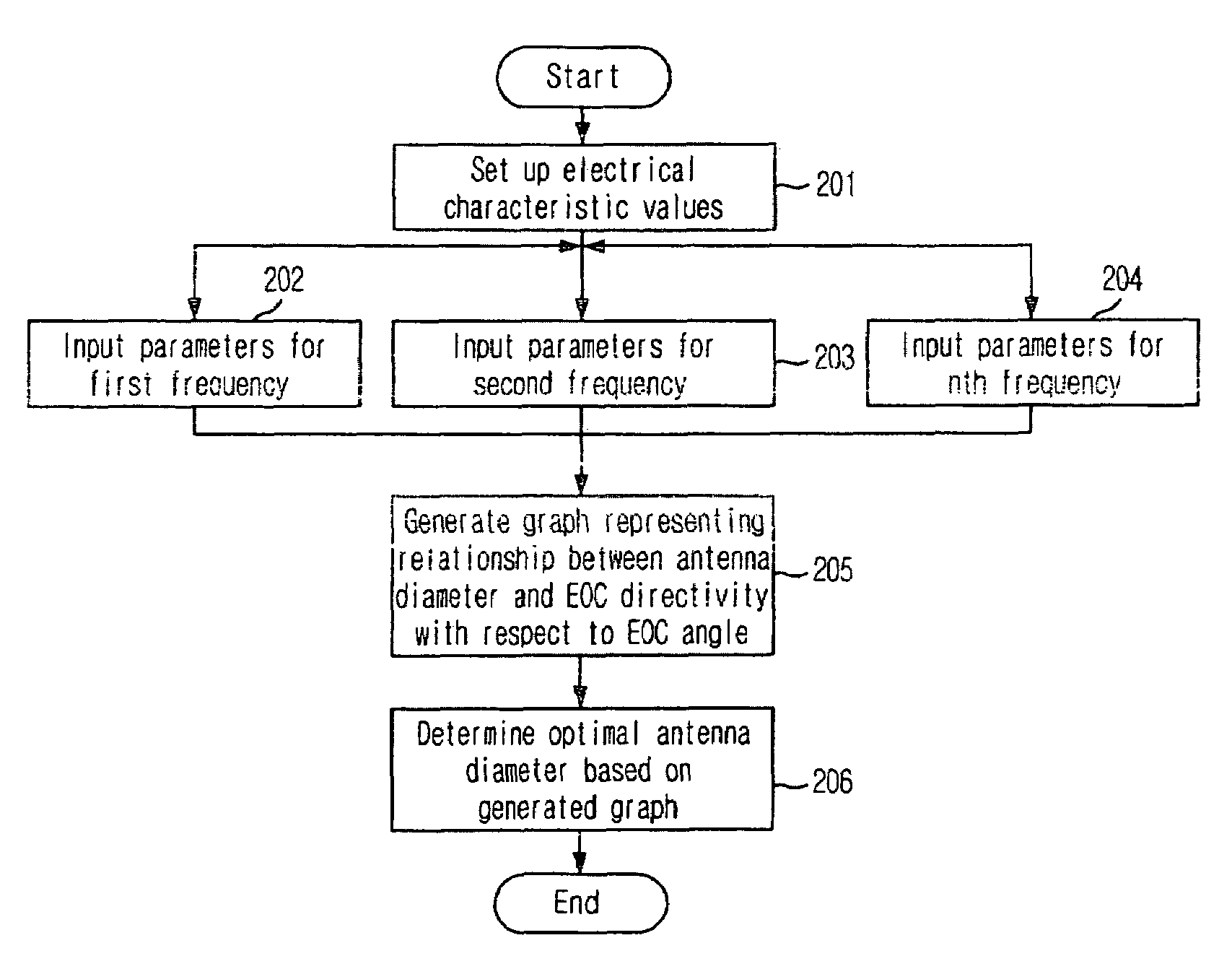
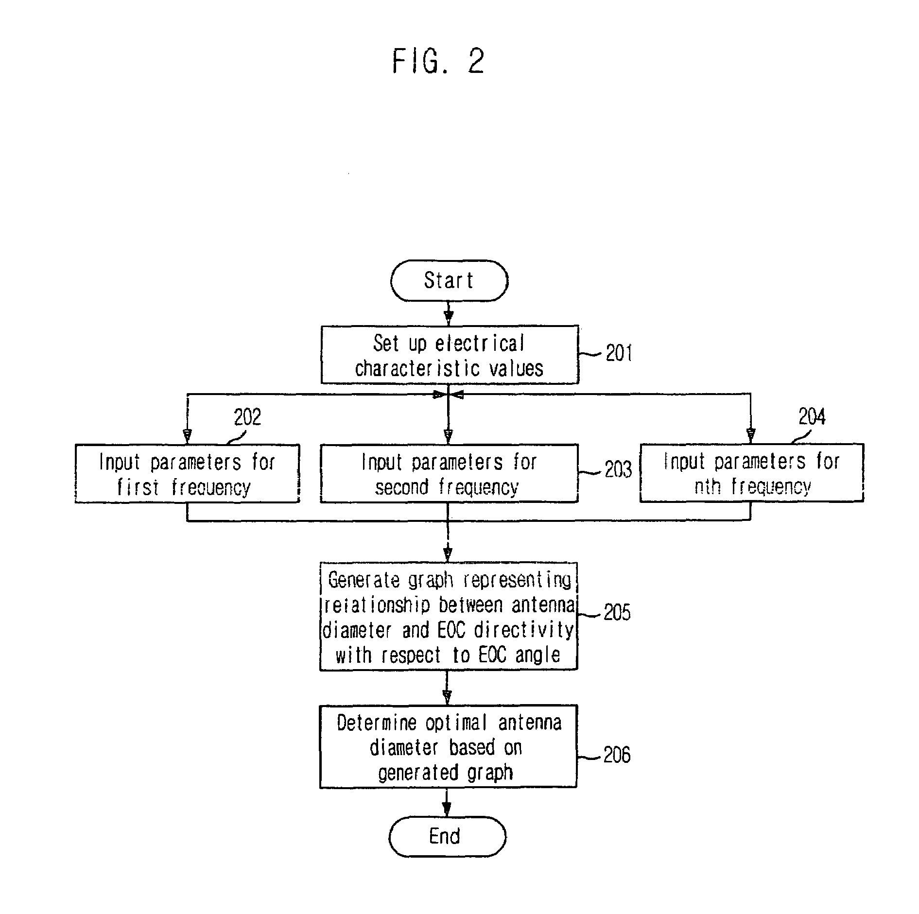
[0023]FIG. 2 shows a flowchart for describing a method for determining a diameter of a reflector antenna mounted on communication satellite in accordance with a preferred embodiment of the present invention, wherein a procedure for determining a diameter of a parabolic antenna accommodating an n-number of frequencies is illustrated.

[0024]First of all, the process of the invention sets up electrical characteristic values ...


PUM


Abstract

Provided are an apparatus and method for determining a diameter of a reflector antenna. The apparatus includes a setting unit for setting up electrical characteristic values of the reflector antenna upon receipt thereof from outside, a parameter input unit for receiving a frequency, an antenna diameter variable value, antenna efficiency, Edge Taper (ET), and an Edge Of Coverage (EOC) angle as parameters for each of multiple frequencies to be accommodated in the reflector antenna, a graph generator for generating, on one rectangular coordinate, a graph representing the relationship between an antenna diameter and EOC directivity with respect to the EOC angle based on the parameters for each frequency received through the parameter input unit, an antenna diameter determination unit for determining an antenna diameter that simultaneously meets the preset EOC directivities for the frequencies to be accommodated in the reflector antenna by using the graph generated by the graph generation unit, and a graph output unit for mapping and outputting the graph generated by the graph generation unit on one rectangular coordinate with an antenna diameter axis and an EOC directivity axis to thereby represent the antenna diameter determined by the antenna diameter determination unit on the graph.

Description

TECHNICAL FIELD[0001]The present invention relates to an apparatus for determining a diameter of a reflector antenna and a method therefor; and, more particularly, to an apparatus and method which are capable of easily and rapidly determining an optimal antenna diameter by expressing Edge Of Coverage (EOC) directivity required for multiple frequencies on one rectangular coordinate in designing the reflector antenna.BACKGROUND ART[0002]Generally, in reflector antenna mounted on communication satellite, a diameter thereof is determined so that it has an optimal EOC gain. In particular, a parabolic antenna accommodating two or more frequencies adjusts a diameter of aperture in order to meet EOC directivity at the two frequencies.[0003]In a conventional method for determining a diameter of such reflector antenna mounted on communication satellite, pattern results for each frequency are analyzed by calculating a frequency, a predetermined antenna diameter and antenna structure data as in...

Claims


Application Information

Patent Timeline
Patent Type & Authority Patents(United States)
IPC IPC(8): G01R23/00
CPCG01B21/10H01Q19/132H01Q15/141H01Q15/16
Inventor LEE, JEOM-HUNKIM, JAE-HOONLEE, HO-JIN
Owner ELECTRONICS & TELECOMM RES INST
Why Eureka
Try Eureka