Pneumatic strapping apparatus

a technology of pneumatic action and strapping apparatus, which is applied in the directions of packaging, packaging, and bundling articles, etc., can solve problems such as unsatisfactory effects

a technology of pneumatic action and strapping apparatus, which is applied in the directions of packaging, packaging, and bundling articles, etc., can solve problems such as unsatisfactory effects

US9630730B2Active Publication Date: 2017-04-25FROMM HLDG

Image

  • Pneumatic strapping apparatus
  • Pneumatic strapping apparatus
  • Pneumatic strapping apparatus

Examples


Embodiment Construction

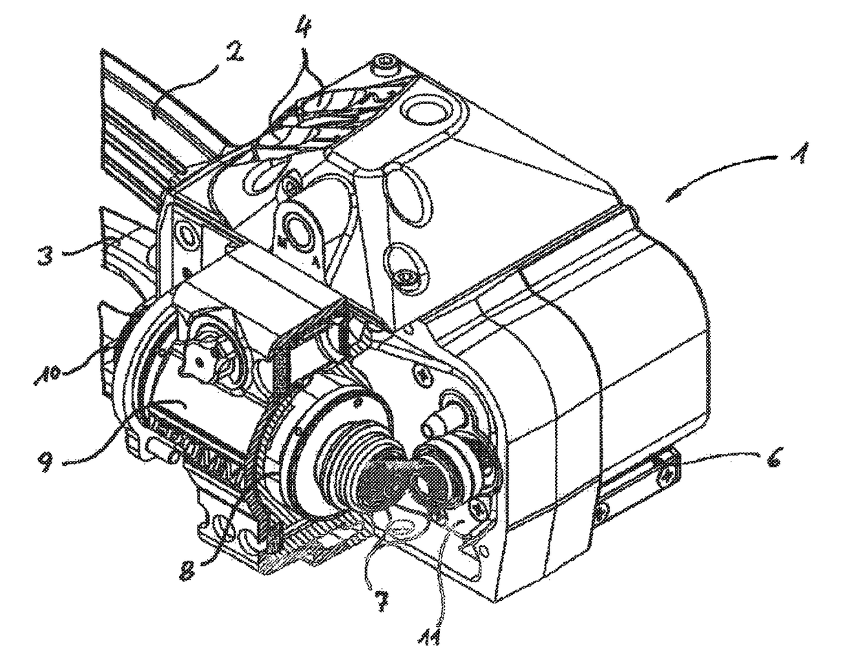
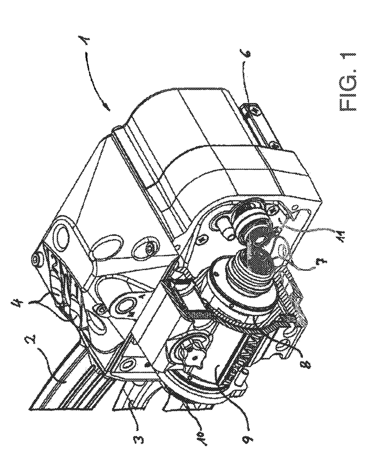
[0031]In FIG. 1, the perspective view of the working head of a pneumatically actuated strapping apparatus can be seen. Mounted on this working head is a handle 2, by means of which the strapping apparatus is handled. Beneath this handle is here found an actuating lever 3, by means of which, together with the actuation of push buttons 4, the pneumatic strapping apparatus is controlled.

[0032]In the use of the strapping apparatus, a plastics tape is guided through a slot 6 situated on the away-facing side in FIG. 1. The plastics tape is then placed around a package to be strapped and is then guided once again through the slot 6. The plastics tape is thus placed in a loop around the package.

[0033]The plastics tape is then tautened via a motorized friction wheel, so that it lies tightly around the package. Finally, the plastics tape, at a position within the strapping apparatus on which it overlaps after formation of the loop, is then compressed to form a connecting point

[0034]At this po...


PUM


Abstract

A pneumatically actuated strapping apparatus for strapping plastic tape around a packaging item including a motorized tensioning device and a motorized welding device for the plastic tape. The tensioning device and the welding device are driven by the same pneumatic motor. The direction of rotation of the pneumatic motor can be inverted. The pneumatic motor is connected to the devices by two freewheeling mechanisms releasing the devices in opposite directions. In order to keep power consumption for evacuating non-operational air low, in a particularly preferred embodiment, switching valves which automatically discharge the nonoperational air to the exterior are integrated into the air intake ducts that are used as evacuation ducts for the non-operational air when the direction of rotation is inverted.

Description

CROSS-REFERENT TO RELATED APPLICATIONS[0001]This is a Continuation application under 37 CFR 1.53(b) of PCT International Patent Application No. PCT / EP2012 / 005293, filed Dec. 20, 2012 entitled PNEUMATIC STRAPPING APPARATUS, which claims the benefit of German Application Serial No. 10 2011 122 155.0 filed Dec. 23, 2011, the entire contents of each of which are herein incorporated by reference.BACKGROUND INFORMATION[0002]The invention relates to a pneumatically actuated strapping apparatus for strapping a plastics tape around a package, including a motorized tensioning device and a motorized welding device for the plastics tape.[0003]Apparatus of this type are known. The plastics tape is firstly placed in a loop around a package, wherein a first, free end forms at a welding point a bottom band. The other end of the plastics tape loop is guided as a top band, together with the bottom band, at a connecting point through the welding device, and subsequently runs to the tensioning device. ...

Claims


Application Information

Patent Timeline
25 Apr 2017
Publication
US9630730B2
IPC
B65B13/18; B65B13/32; B65B13/02
CPC
B65B13/188; B65B13/025; B65B13/322
Inventors
LEPPERT, KLAUS