
Actuation device for a flap

a technology of actuation device and flap, which is applied in the direction of locking applications, mechanical devices, fastening means, etc., can solve the problems of undesired noise generation, inability to open the filler-neck flap, and reducing convenience, so as to improve operating convenience, simple and robust construction, and simple integration into the central locking device

Active Publication Date: 2017-04-25
ILLINOIS TOOL WORKS INC
View PDF18 Cites 5 Cited by
  • Summary
  • Abstract
  • Description
  • Claims
  • Application Information

AI Technical Summary

Benefits of technology

The invention provides an actuation device for a flap that is simple and robust, and can be easily integrated into a central locking device of an automobile. The device has a high sealing action against moisture or dirt, and is designed to prevent unintentional opening of the flap. The actuation device can be flexibly adapted within wide limits to the respective requirements, and is also suitable for use in self-opening flap systems. The actuation device is preloaded during the first stroke, and a spring force is applied during the second stroke to ensure secure arresting of the flap. The actuation device can be powered by a simple and flexible design, and is designed to be easily integrated into existing systems. The locking means of the actuation device can be a drive means and at least one locking element that is moveable in a radial direction with respect to the axial moving direction of the first actuation part. The locking element can engage in a positively locking manner with the first or second actuation part, and can also be retracted out of a reception to allow for axial movement of the first actuation part. The actuation device is thus designed to be simple, robust, and flexible, while still providing effective sealing and increased operating convenience.

Problems solved by technology

This can reduce convenience.
Furthermore, with the relatively high spring forces, undesired noise generation can arise during the actuation.
Furthermore, it is often sought to couple filler-neck flaps to the central locking device of an automobile, such that when the automobile is locked, the filler-neck flap cannot be opened.
Since it is the case in the known device that the filler-neck flap is held in the closed position only by a spring force, relatively complex additional measures are required for this purpose.

Method used


Image

  • Actuation device for a flap
  • Actuation device for a flap
  • Actuation device for a flap

Examples


Embodiment Construction

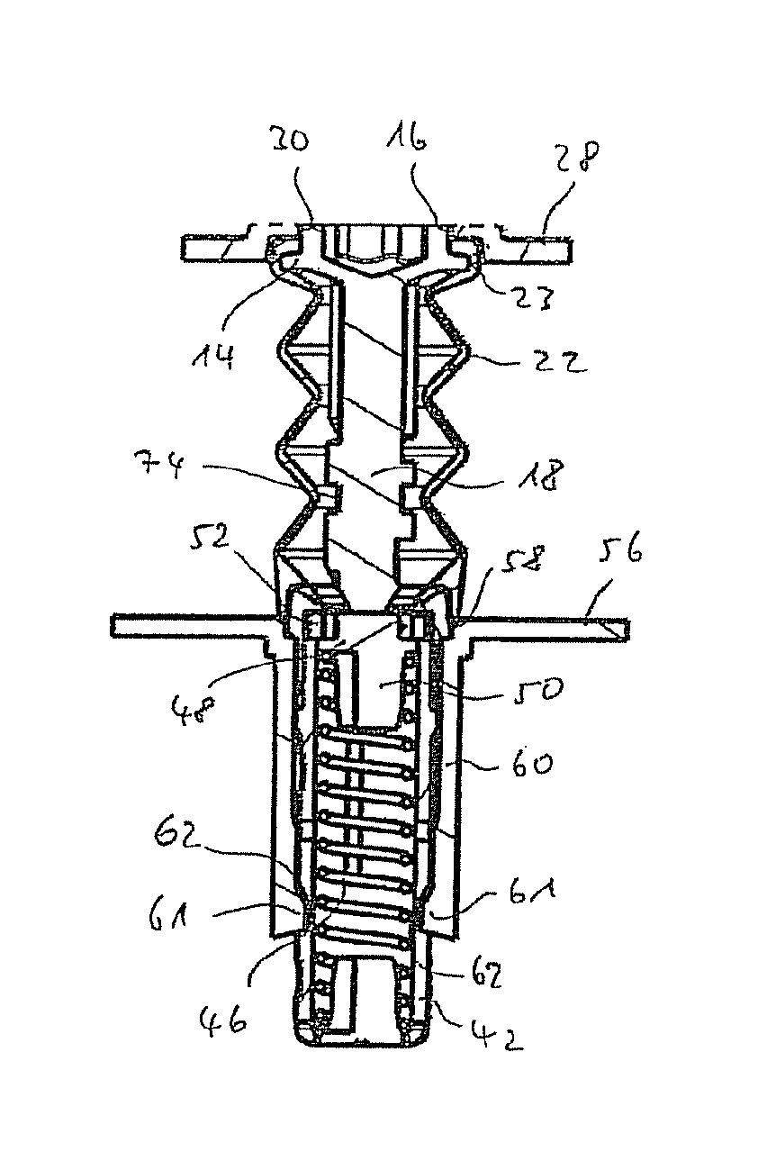
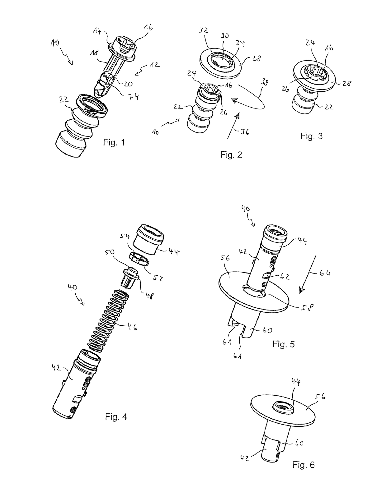
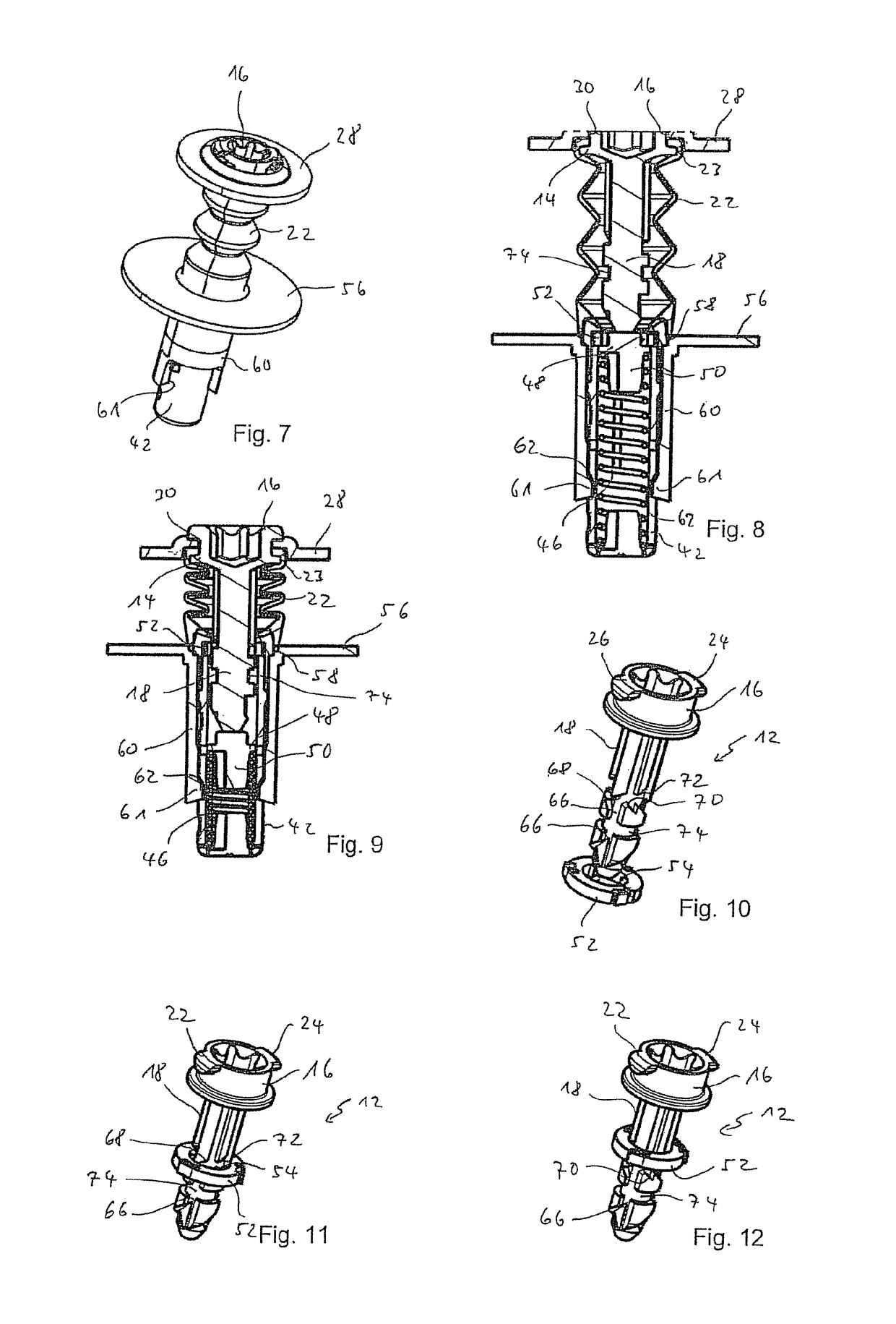
[0052]Unless stated otherwise, the same reference numerals are used to denote identical objects in the figures. As can be seen from FIG. 1, the first actuation part 10 as per the first exemplary embodiment has a tappet 12 having a tappet head 16, which is provided with a flange 14, and having a substantially cylindrical tappet shank 18 which extends from the tappet head 16. On the outer circumference of the tappet shank 18 there is provided a control curve 20 for a push-push kinematic. The first actuation part 10 furthermore comprises an elastic sealing 22 in the form of an elastic bellows which, as can be seen in FIG. 2, is fastened on the tappet 12 so as to provide sealing, and in said state seals off the tappet shank 18 over the entire circumference thereof. FIG. 2 also shows that the tappet head 16 has two locking projections 24, 26 situated diametrically opposite one another. On the tappet shank 18 there is also formed an annularly encircling groove 74, the function of which wi...


PUM


Abstract

An actuation device for a flap mounted pivotably on a compartment, with a push-push kinematic, includes a first actuation part to be fastened on the flap and a second actuation part to be fastened on the component. The first actuation part engages with the second actuation part when the flap is moved from its opened position into its closed position, so that after a first stroke of the first actuation part in the direction of the second actuation part and a subsequent backstroke of the first actuation part, the actuation parts are held on each other in an arresting position. The arresting position is released by a second stroke of the first actuation part in the direction of the second actuation part so that the flap can be moved into its opened position, wherein the first actuation part and the second actuation part are disengaged.

Description

TECHNICAL FIELD[0001]The invention relates to an actuation device for a flap mounted movably on a component between a closed position and an opened position with a push-push kinematic, in particular for a flap in or on an automobile mounted pivotably on a compartment.BACKGROUND ART[0002]It is known for filler-neck flaps, for example, of automobiles to be actuated by means of so-called push-push devices. A corresponding actuation device is known for example from DE 10 2008 057 933 A1. The actuation device is fastened on the filler-neck compartment, wherein said actuation device has an actuation end which projects out of the compartment in the installed state. The known actuation device has an axially movably mounted tappet which has a control curve on its outer circumference. The actuation device furthermore has a housing and a ring mounted axially fixed and rotatable in the housing, which ring has at least one projection on its inner circumference. During operation, the filler-neck ...

Claims


Application Information

Patent Timeline
Patent Type & Authority Patents(United States)
IPC IPC(8): E05C5/04E05B83/34E05C19/02E05C5/02
CPCE05B83/34E05C19/022E05Y2201/22E05Y2201/232E05Y2201/426E05Y2201/474E05Y2800/11Y10T292/0864E05Y2400/3013E05Y2201/221
Inventor BECK, CHRISTIAN
Owner ILLINOIS TOOL WORKS INC
Learn More