Fluid discharge vibration damping strips for acoustic protection of aircraft turbomachine fan casing

a technology of vibration damping strips and turbomachine fans, which is applied in the direction of liquid fuel engines, machines/engines, transportation and packaging, etc., can solve the problems of the screw head released in the jet can cause high damage to the fan vanes, and the risk of failure of some fixing screws of the acoustic panels, etc., to avoid the effect of detrimental consequences and simplify the mounting

Active Publication Date: 2017-04-25
SN DETUDE & DE CONSTR DE MOTEURS DAVIATION S N E C M A
View PDF10 Cites 0 Cited by
  • Summary
  • Abstract
  • Description
  • Claims
  • Application Information

AI Technical Summary

Benefits of technology

[0014]The invention thus provides a simple and high performance solution capable of discharging liquids towards either or both ends of the edges likely to be wetted by such liquids, as oil or kerosene.
[0016]The damping strips are therefore non longer likely to be degraded by the prolonged retention of liquids on their edges, which enables a high performance damping function to be preserved for a long time.
[0019]Preferentially, at least one of the two opposed edges of at least one of the damping strips consists of two successive portions in the direction of the center axis, each of both portions being tilted along the center axis such that liquid present on each of both portions can flow by gravity towards the upstream end and the downstream end respectively. This enables the liquid to be distributed towards both upstream and downstream ends of the edge concerned, and a possible liquid overflow at one of its ends, and a spilling into the jet. In order to evenly distribute the flow onto both ends of the strip, the two tilted portions, arranged as downwardly open V, can be symmetrical.
[0023]This solution avoids the detrimental consequences on the strips in case of a mounting mistake, since in both mounting directions, the edge likely to collect liquids, that is the one oriented upwards, will be able to lead the liquids by gravity up to either or both ends of this edge, to provide for discharge thereof.
[0024]In the same way, and still for the purpose of avoiding detrimental consequences on the bands in the case of a possible mounting mistake, at least one of the damping strips has a first plan of symmetry arranged between the two opposite edges. Preferably, all the strips have an identical shape, which still further simplifies the mounting.

Problems solved by technology

However, risks of failure of some fixing screws of the acoustic panels have been identified.
In case of failure, the screw heads released in the jet can produce high damage to the fan vanes, after ingestion.
These strong stresses transmitted to the screws cause the loosening thereof, and are likely to cause strong wear, even possibly up to failure, as discussed above.
However, the selected material may be sensitive to the contact with liquids such as oil and kerosene, when dipped for a long period.
This prolonged contact with such liquids can indeed cause a risk of degradation of the material and / or an efficiency loss of the damping achieved.
In view of the orientation of the strips in the direction of the longitudinal axis of the engine, a retention of these liquids is then possible on some edges of the strips, which is likely to induce a detrimental prolonged contact.
However, the presence of these grooves can embrittle the strips, in addition to decrease the contact area with the casing, which results in a reduced efficiency.
On the other hand, the presence of these grooves can also decrease the stiffness of the strips when they are compressed, which is also likely to impact their damping ability.
Consequently, this solution is not fully satisfactory.

Method used


Image

  • Fluid discharge vibration damping strips for acoustic protection of aircraft turbomachine fan casing
  • Fluid discharge vibration damping strips for acoustic protection of aircraft turbomachine fan casing
  • Fluid discharge vibration damping strips for acoustic protection of aircraft turbomachine fan casing

Examples


Embodiment Construction

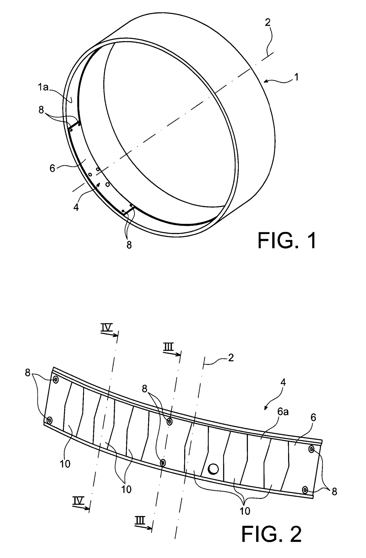
[0036]First in reference to FIG. 1, is represented a fan casing 1 intended to be an integral part of a front part of an aircraft turbojet engine, preferably of the two flow twin-spool type.

[0037]The casing assumes a conventional ferrule shape, with a longitudinal axis 2 corresponding to the longitudinal axis of the turbojet engine assembly.

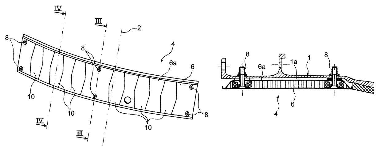
[0038]At its upstream end, the internal surface 1a of the casing 1a is equipped with a plurality of acoustic protection devices 4, only one of which has been represented in FIG. 1.

[0039]This device 4 includes an acoustic protection panel 6 forming a ferrule sector centered on a center axis the same as the longitudinal axis 4. When all the protection devices are installed on the casing, their panels 6 located in the continuity of each other along the circumferential direction form an internal acoustic protection ring together.

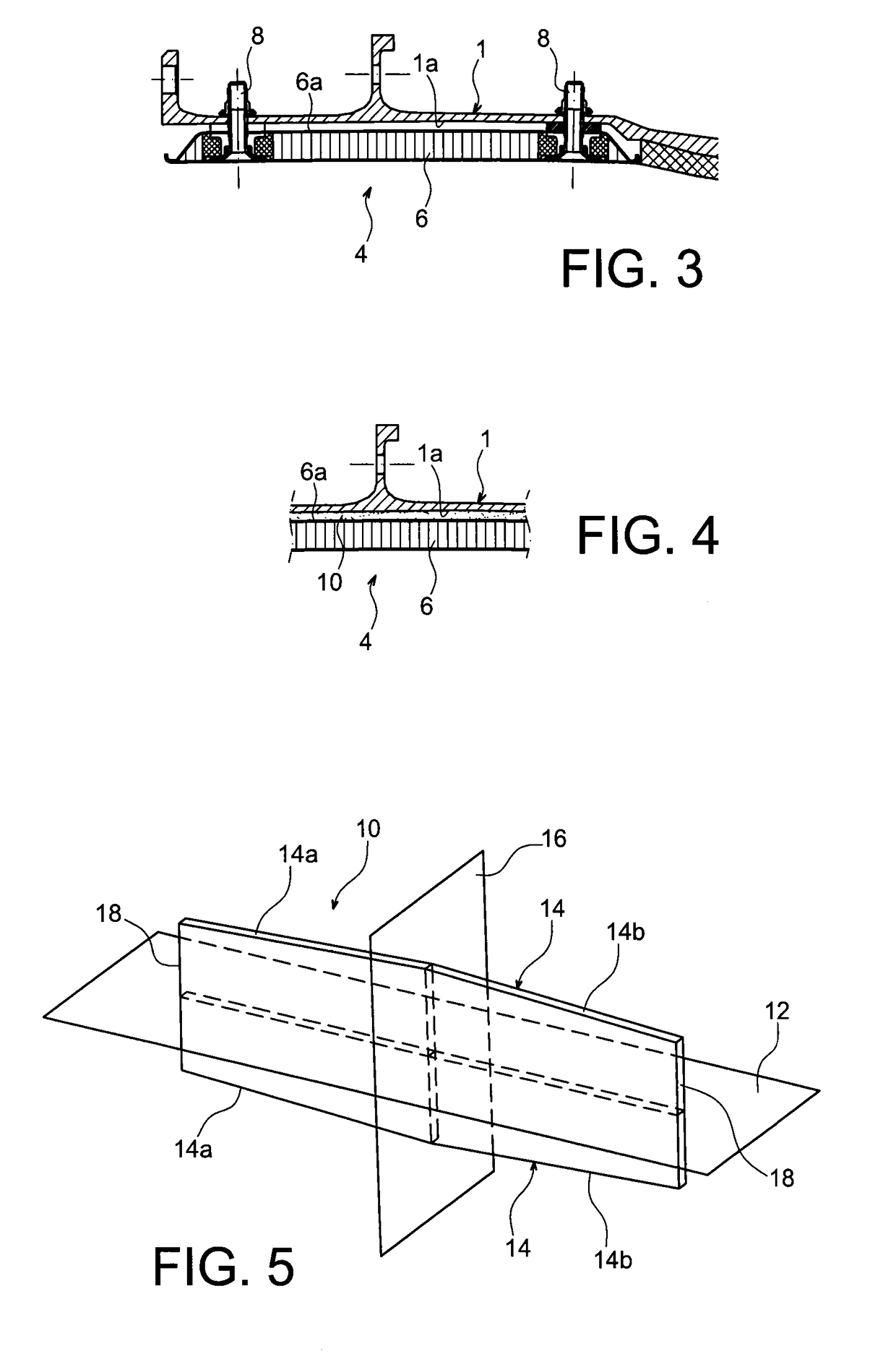
[0040]The panel 6 is preferentially assembled by screwing on the casing, the fixing screws 8 being mounted hidden in the pan...


PUM


Abstract

An acoustic protection device for a fan casing of an aircraft turbomachine, including an acoustic protection panel forming a ferrule sector centered on a center axis, and one or more vibration damping strips pressed on a first side to an external surface of the panel and on a second side to an internal surface of the casing, each damping strip including two opposite edges each including an upstream end and a downstream end spaced from each other along a direction of the center axis. At least one of both opposite edges of at least one of the damping strips is shaped such that liquid present on this edge can flow by gravity towards either or both of its upstream and downstream ends.

Description

TECHNICAL FIELD[0001]The invention relates to the mounting of an acoustic protection inside an aircraft turbomachine fan casing. More particularly, the invention is concerned with the vibration damping strips provided between the fan casing and the acoustic panels.[0002]The invention is applicable to any type of aircraft equipped with a fan casing, in particular turbojet engines.STATE OF PRIOR ART[0003]On current turbojet engines, acoustic protection panels are generally assembled on the internal surface of the fan casing, about the engine axis. The assembly is usually performed by screwing panels to the casing.[0004]However, risks of failure of some fixing screws of the acoustic panels have been identified. In case of failure, the screw heads released in the jet can produce high damage to the fan vanes, after ingestion. Among the main causes identified, there are the strong vibratory stresses induced by the coincidence between a fundamental mode of the acoustic panel and an excitat...

Claims


Application Information

Patent Timeline
Patent Type & Authority Patents(United States)
IPC IPC(8): F04D29/66F01D25/32F02C7/045F04D19/00B64D33/02
CPCB64D33/02F01D25/32F02C7/045F04D19/002F04D29/663F04D29/668B64D2033/0206F04D29/66
Inventor ROFFI, GUILLAUMETRAN, JULIEN
Owner SN DETUDE & DE CONSTR DE MOTEURS DAVIATION S N E C M A
Why Eureka
Try Eureka