
Transmission module

Inactive Publication Date: 2006-11-07
VOITH TURBO GMBH & CO KG
View PDF15 Cites 12 Cited by
  • Summary
  • Abstract
  • Description
  • Claims
  • Application Information

AI Technical Summary

Benefits of technology

[0006]Therefore the invention is based on the object of creating a transmission module system including a majority of transmission modular units, particularly compound transmission modular units in such a way that using the same modules with little expenditure and maintaining a high degree of standardization transmission modular units can be created for a multitude of different purposes. The individual modular unit of the module itself should be mechanically convertible without having to adjust sensors, actuators, ECU, cabling. The prefabrication, i.e. the number of production steps until the final test and the performance of maintenance steps using simple personnel should be reduced.
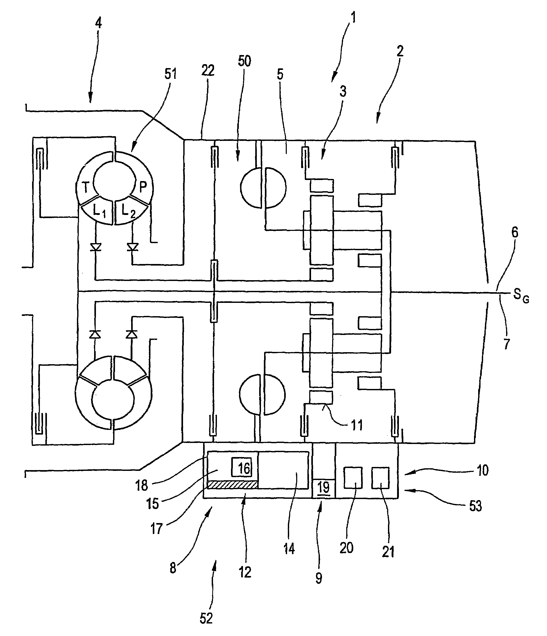
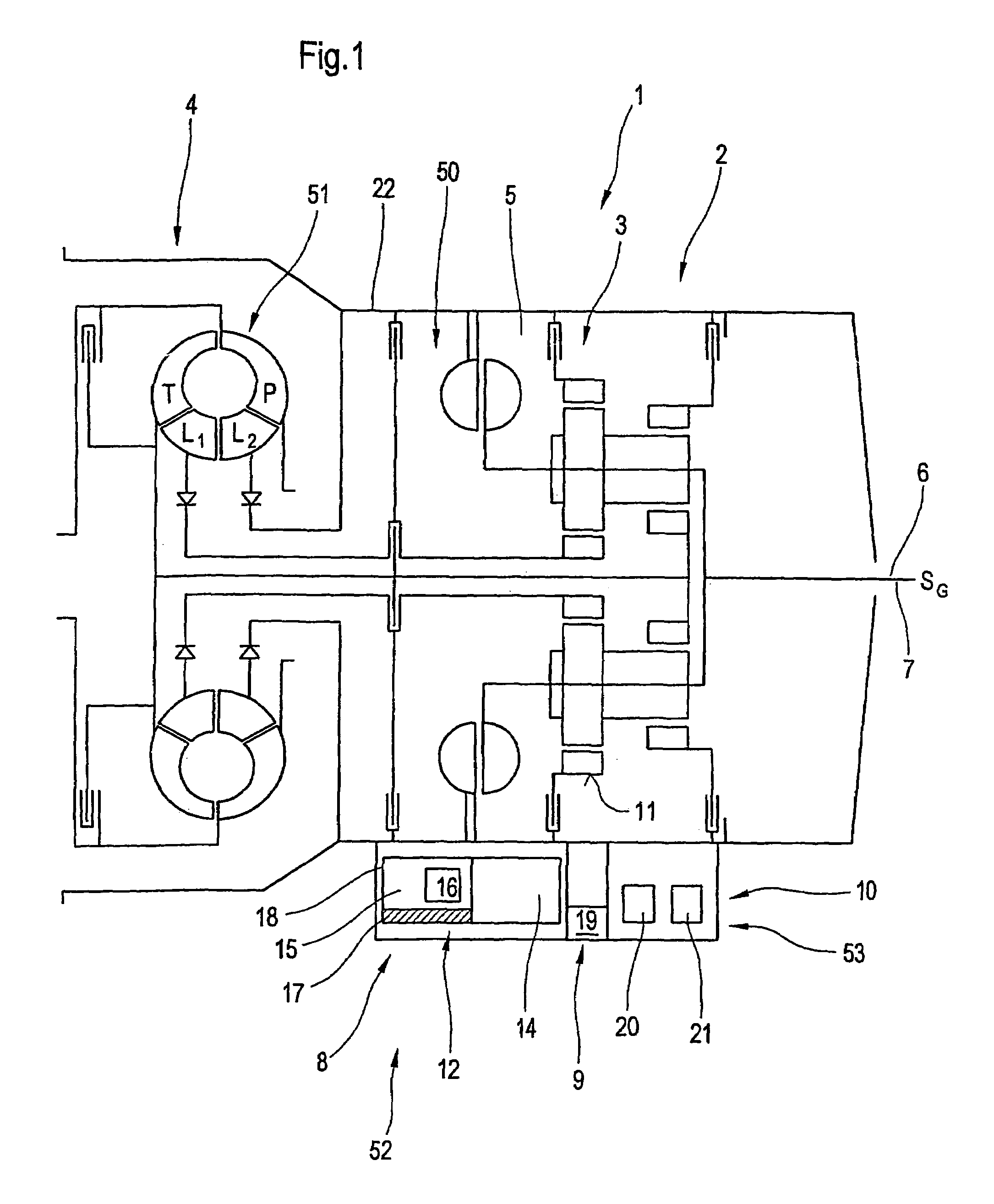
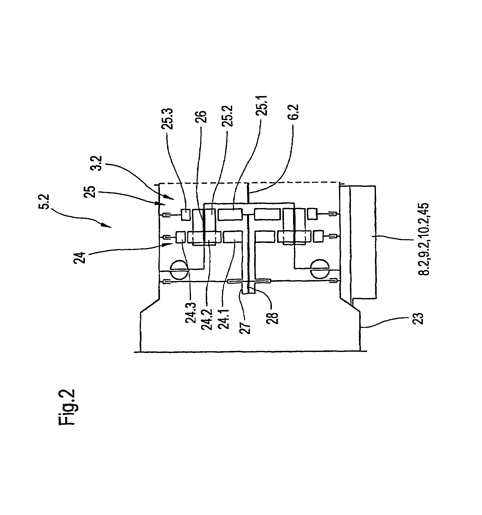
[0017]In a particularly advantageous design of the basic transmission module and therewith the mechanical transmission part this comprises two planetary wheel planes for realization of three gear steps, whereby both are coupled with each other and use a common element, preferably in the form of the bridge, whereby said bridge simultaneously forms the outlet of the basic transmission module. In the formation of the closing unit as a simple cover element without possibility of integrating further power-transferring elements the compound transmission is designed as a 3-speed transmission. The integration of the rear-mounted step into the closing unit, in combination with the two planetary wheel planes of the basic transmission module makes possible a very compact overall transmission modular unit for examples of application in which the operating range should be covered by at least four to six gears.
[0025]The arrangement of the controller in fitting position in the lower area of the transmission modular unit and the provision of a corresponding case make it possible to arrange the sensors for recording the individual variables at least indirectly describing the operation of the individual elements of the transmission modular unit at a specified time likewise in the area underneath the transmission center line which corresponds to the axis of rotation and therewith makes it possible to design the entire control device including the sensor system and actuator system relatively compactly. The arrangement in the operating fluid, control fluid and / or lubricant sump, which as a rule is collected in a so-called oil pan, which is formed by the bottom part of the transmission case, in the present case of the case element of the body transmission, makes it possible additionally to remove the control device complete with the related control hydraulics, the actuator system for operation of the individual switch elements and the sensors as well as the supply devices, elements, filters etc. which as a rule are arranged on the case of the oil pan in simple fashion and test them separately as a whole of operating ability possibly additionally under specified predefinable conditions.

Problems solved by technology

In addition, a simple interchangeability of the sensor system in the total transmission, i.e. 3-speed, 4-speed or 6-speed transmission for the hydraulic control devices as well as the sensor system is not possible without further ado, without taking the transmission module apart.

Method used


Image

  • Transmission module
  • Transmission module
  • Transmission module

Examples


Embodiment Construction

[0036]FIG. 1 illustrates in diagramatically simplified representation the basic principle of the invention's transmission module system in the form of a basic transmission module 5 in compact fashion in a complete transmission modular unit 1. In the case of the transmission modular units it is a matter preferably of compound transmissions 2, which comprise at least one mechanical transmission part 3, which is coupled with a drive unit 51 in the form of a hydrodynamic transmission part or a hydrostatic transmission part 4. The basic version of the combination 50 out of basic transmission module 5 and drive unit 51 in the form of a hydrodynamic transmission part 4 represents a version for realization of at least three gear steps. The related mechanical transmission parts 3 and the hydrodynamic transmission part 4 or the hydrostatic transmission part are combined into one structural unit out of a basic transmission module 5 and drive unit 51. The basic transmission module 5 has an outl...


PUM


Abstract

A modular transmission system for the production of a plurality of modular transmission units that are modified for different applications purposes, comprising a transmission input and transmission output a power transmitting element comprising a mechanical transmission part that is arranged in a housing part and that forms with the latter a basic transmission module that includes at least one input and one output, and a control and supply unit integrated into the basic transmission module. The logic, control and supply units are arranged beneath the power transmitting element of the basic transmission module.

Description

BACKGROUND OF THE INVENTION[0001]The invention relates to a transmission modular system.[0002]Transmission modular units are known in a multitude of designs for various purposes. As representatives, reference is made to the following:[0003]Juergen Pickard: “Planetary transmission in automatic vehicle transmissions”, Automobilindustrie 4 / 79, Pages 41 through 48[0004]To do justice to a broad spectrum of applications, increasingly transmission modules or transmission modular systems are being developed. Such a transmission module is known from the cited state of the art, Page 47. This transmission module allows the assembly of multi-speed transmissions. The transmission module comprises thereby the individual structural components of hydrodynamic transmission elements in the form of a hydrodynamic speed / torque converter, a hydrodynamic retarder, a front-mounted range-change unit, a basic transmission module in the form of a main transmission for realization of 3 speeds and a rear trans...

Claims


Application Information

Patent Timeline
IPC IPC(8): F16H57/08F16H57/02F16H3/66F16H57/033F16H61/00
CPCF16H57/033F16H61/0009F16H3/66F16H57/0402F16H57/0434F16H2057/02013F16H2057/02047F16H2200/2025F16H2057/0335
Inventor KOMER, TILLMANKNOBLAUCH, IRISTONEATTO, MARCOEUBLER, HANS-PETERNEUWIRTH, HEIKOKOMER, ALEXANDERHELLMICH, JOACHIM
Owner VOITH TURBO GMBH & CO KG
Learn More