Radiator module

a technology of radiator modules and radiators, applied in the direction of stationary conduit assemblies, heat exchange apparatus, light and heating equipment, etc., can solve the problems of adding weight and size to the radiator modules, and production costs

Active Publication Date: 2017-04-25
TITANX HLDG AB
View PDF17 Cites 5 Cited by
  • Summary
  • Abstract
  • Description
  • Claims
  • Application Information

AI Technical Summary

Benefits of technology

[0011]It is preferred to arrange said plate by snap fitting it inside of said one of the first tanks by means bosses before assembly of said one of the first tanks with said first core. It is obvious that snap fitting is easy to accomplish and that handling of the tank during assembly with the plate snap fitted inside is facilitated considerably.
[0014]According to a preferred embodiment of the invention all tanks are of identical design with opposing ports used as an inlet and / or outlet or plugged by means of a cap. It is obvious to the person skilled in the art that tanks of identical design help to reduce manufacturing costs and improve logistics.
[0015]Preferably, with tanks of identical design, one of said ports of each tank comprises a hose flange, wherein the hose flanges of said inlet tanks and the hose flanges of said outlet tanks are facing each other and are interconnected by means of hose pieces. Clearly, junctions of that kind between the tanks involved are both simple to accomplish and furthermore vibration proof, which is further improved by forming said hose flanges as integral parts of said tanks.
[0016]With tanks of identical design, preferably one of said ports of each tank comprises a mounting flange on which is mountable a coolant inlet or outlet duct or a cap. Thus, the tank involved is easy to adapt to its task in the radiator module ready for use.
[0017]In order to eliminate the risk of incorrect assembly when tanks of identical design are used said one of the first tanks comprising the perforated plate, which is not visible after assembly of said one of the first tanks with the first core, has a color marking separating it from the remaining tanks. Preferably, when all tanks are made of plastics, said color marking comprises use of a differently colored resin for said one of the first tanks.

Problems solved by technology

However, it is obvious too that the manifolds 11, 15 add some weight and size to the radiator module 1 as well as production costs.

Method used


Image

  • Radiator module
  • Radiator module
  • Radiator module

Examples


Embodiment Construction

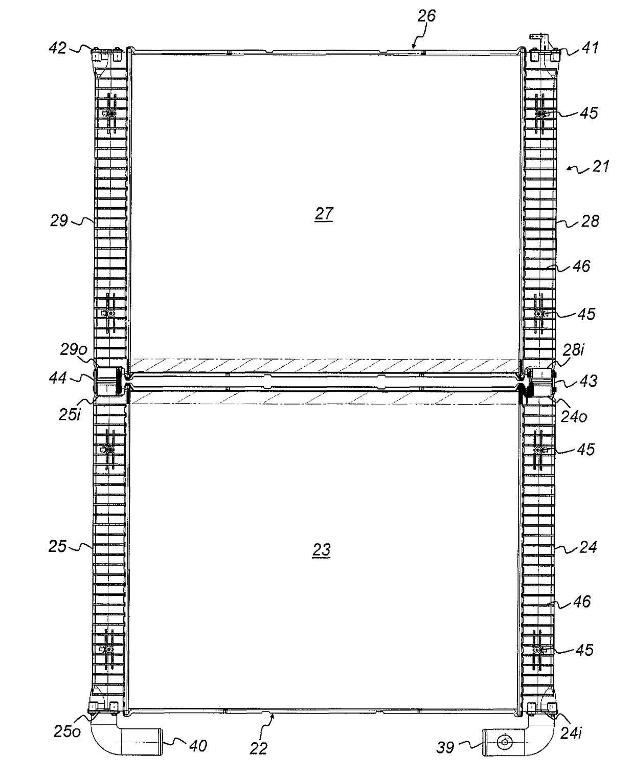
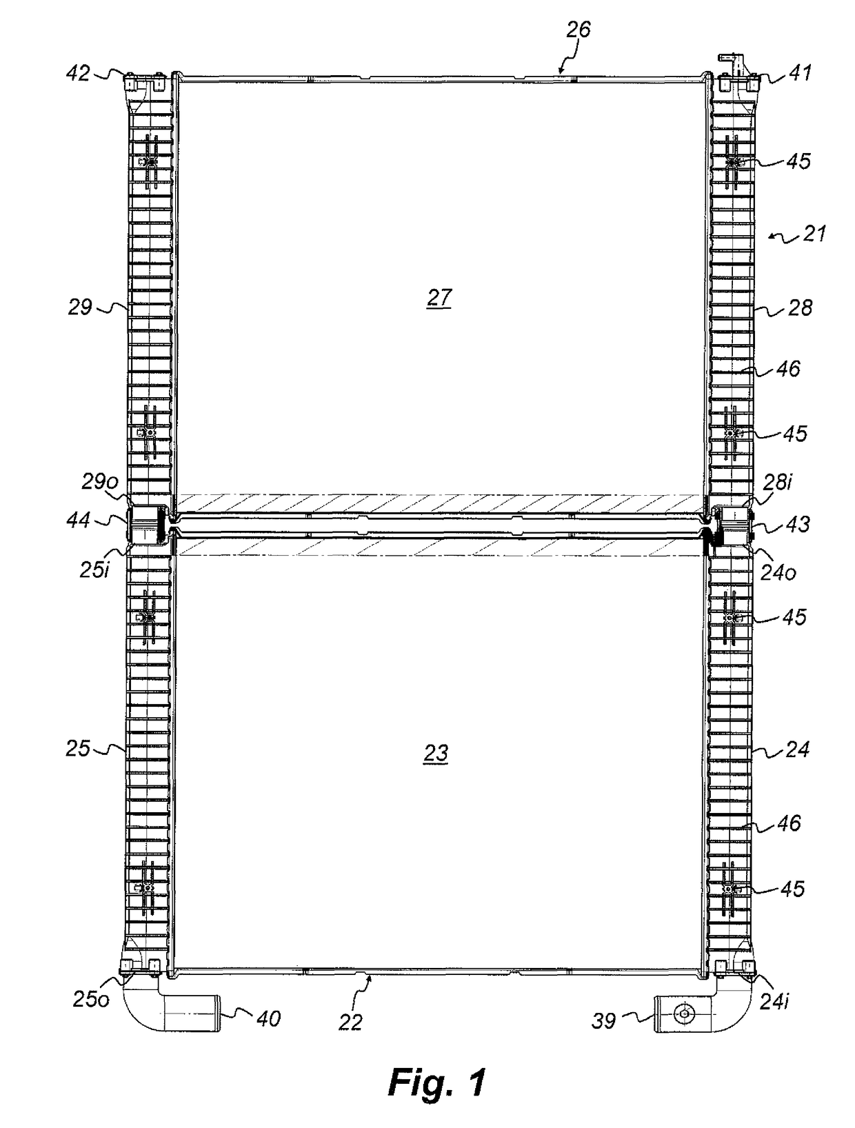
[0027]A prior art radiator module 1 has been described in detail hereinbefore. The radiator module 21 according to the preferred embodiment of the invention has several features in common with it. Thus said embodiment comprises a first or lower radiator 22, having a first or lower core 23 connected between a first or lower inlet tank 24 and a first or lower outlet tank 25, and a second or upper radiator 26, having a second or upper core 27 connected between a second or upper inlet tank 28 and a second or upper outlet tank 29. Both radiators 22, 23 are of identical size and have identical cores 23, 27 and almost identical coolant tanks 24, 25, 28, 29, although the orientation of said tanks differs in a way described later on, where only placement of the radiators 22, 26 on top of each other is considered.

[0028]Differing from prior art the 1 radiator module 21 according to the invention does not comprise any manifolds. Instead it comprises a coolant inlet duct 39, which is connected d...


PUM


Abstract

A radiator module having a coolant inlet duct and a coolant outlet duct and two radiators. The first radiator has a first core connected between a first inlet tank and a first outlet tank and the second radiator has a second core connected between a second inlet tank and a second outlet tank. The coolant inlet duct is connected to a coolant inlet of the first inlet tank and the coolant outlet duct is connected to a coolant outlet of the first outlet tank. According to the invention a coolant outlet of the first inlet tank is connected to a coolant inlet of the second inlet tank, a coolant inlet of the first outlet tank is connected to a coolant outlet of the second outlet tank and a flow restrictor is provided in one of the first tanks in front of the first core, such that the coolant flow between the core and said one of the first tanks is restricted.

Description

TECHNICAL FIELD[0001]The present invention concerns a radiator module comprising a coolant inlet duct and a coolant outlet duct and two radiators, the first radiator having a first core connected between a first inlet tank and a first outlet tank and the second radiator having a second core connected between a second inlet tank and a second outlet tank, wherein said coolant inlet duct is connected to a coolant inlet of the first inlet tank and said coolant outlet duct is connected to a coolant outlet of the first outlet tank.PRIOR ART[0002]A prior art radiator module 1 according to the preamble is shown in FIG. 6 in an elevational view. It comprises a first or lower radiator 2 having a first or lower core 3 connected between a first or lower inlet tank 4 and a first or lower outlet tank 5 and a second or upper radiator 6 having a second or upper core 7 connected between a second or upper inlet tank 8 and a second or upper outlet tank 9. There is a coolant inlet duct 10 comprising a ...

Claims


Application Information

Patent Timeline
Patent Type & Authority Patents(United States)
IPC IPC(8): F28F9/26F28F9/02F28D7/02F28D1/04
CPCF28D1/0417F28F9/0224F28F9/0278F28F9/262F28D1/0443F28D1/05341F28F9/02
Inventor CONTET, ARNAUDAKESSON, KRISTIANLEYDET, JEAN-BAPTISTE
Owner TITANX HLDG AB
Why Eureka
Try Eureka