Connector

a technology of connecting rods and contacts, applied in the direction of coupling contact members, fixed connections, coupling device connections, etc., can solve the problems of inability to establish reliable electrical conduction, inability to give sufficient contact pressure, and significant uneven /b>, etc., and achieve reliable electrical conduction

Active Publication Date: 2017-04-25
JAPAN AVIATION ELECTRONICS IND LTD
View PDF10 Cites 7 Cited by
  • Summary
  • Abstract
  • Description
  • Claims
  • Application Information

AI Technical Summary

Benefits of technology

[0009]The present invention has been made to overcome the above problem associated with the prior art and aims at providing a connector that can establish reliable electrical conduction even when a counter-connector contact is engaged as being positioned improperly.
[0011]wherein the socket contact includes: one or more pairs of conduction contact points that are disposed respectively on both sides of the fitting plane so as to face each other across the fitting plane in an elastically displaceable manner and that come into contact with and are electrically connected to the counter-connector contact; and one or more pairs of displacement regulator contact points that are disposed respectively on both sides of the fitting plane so as to face each other across the fitting plane and that come into contact with the counter-connector contact when the counter-connector contact shifts, thereby preventing the counter-connector contact from shifting by more than a predetermined amount,

Problems solved by technology

However, in a case where insertion position is improper, such as when the counter-connector contact is inserted off the fitting plane or inserted obliquely with respect to the fitting plane, the spring contact point of the socket contact possibly shifts beyond its elastic limit so as to cause plastic deformation of a spring piece on which the spring contact point is formed, or sufficient contact pressure cannot possibly be given between the counter-connector contact and the socket contact, whereby there is a concern that reliable electrical conduction cannot be established.
If the position of the counter-connector contact largely deviates from the fitting plane C1 in the vicinity of the upper end of the beam 2, the contact state of the counter-connector contact with the pair of spring contact points 4 would be significantly uneven; one of the spring contact points 4 would shift so much that the corresponding spring piece 3 would easily plastically deform, and the other spring contact point 4 would be separated from the counter-connector contact and possibly result in contact failure.
Hence, a problem that the reliable electrical conduction is impaired would arise.

Method used


Image

  • Connector
  • Connector
  • Connector

Examples


embodiment 1

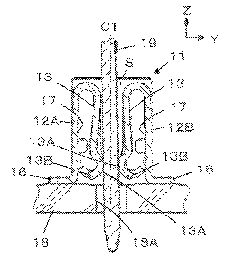
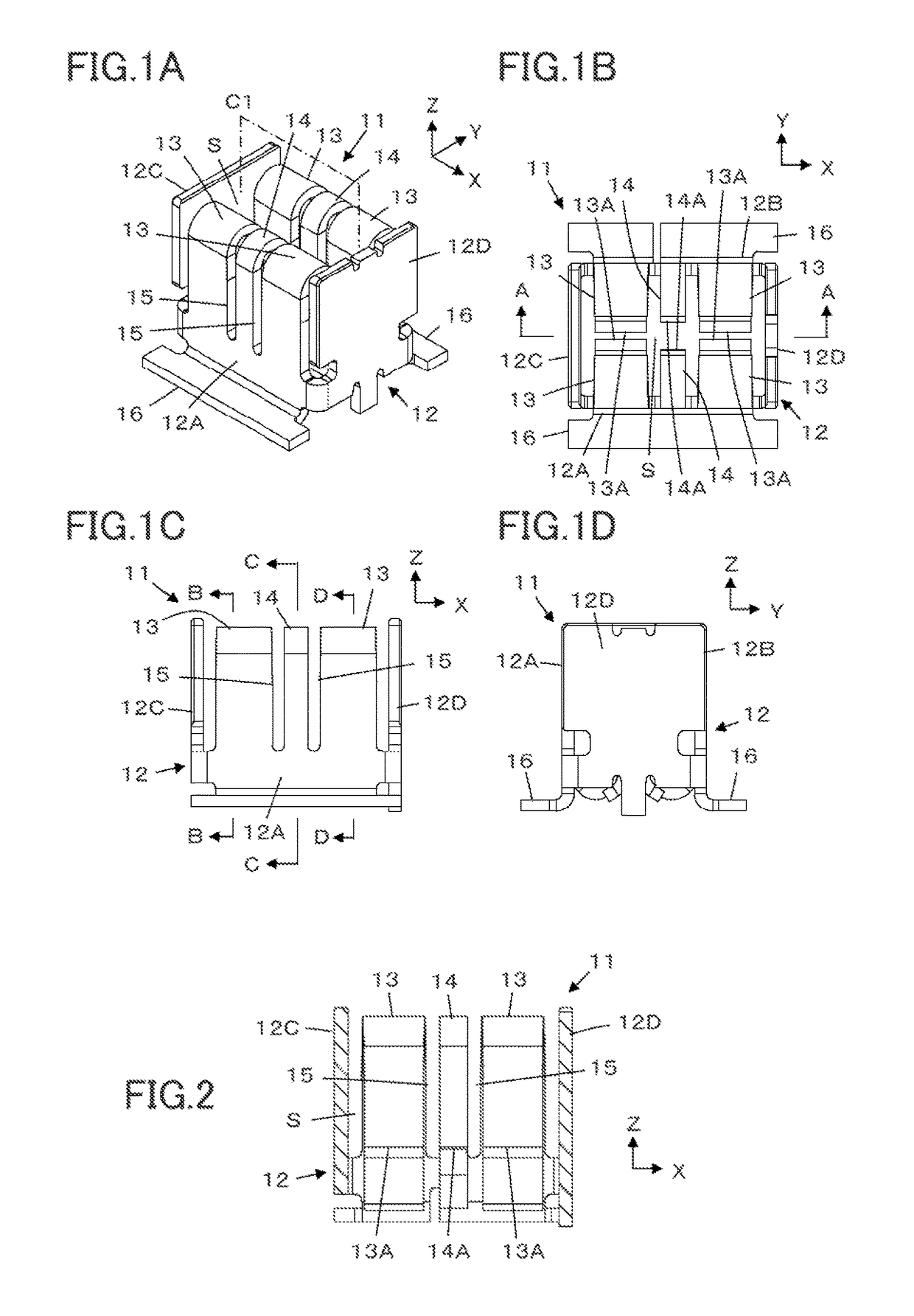
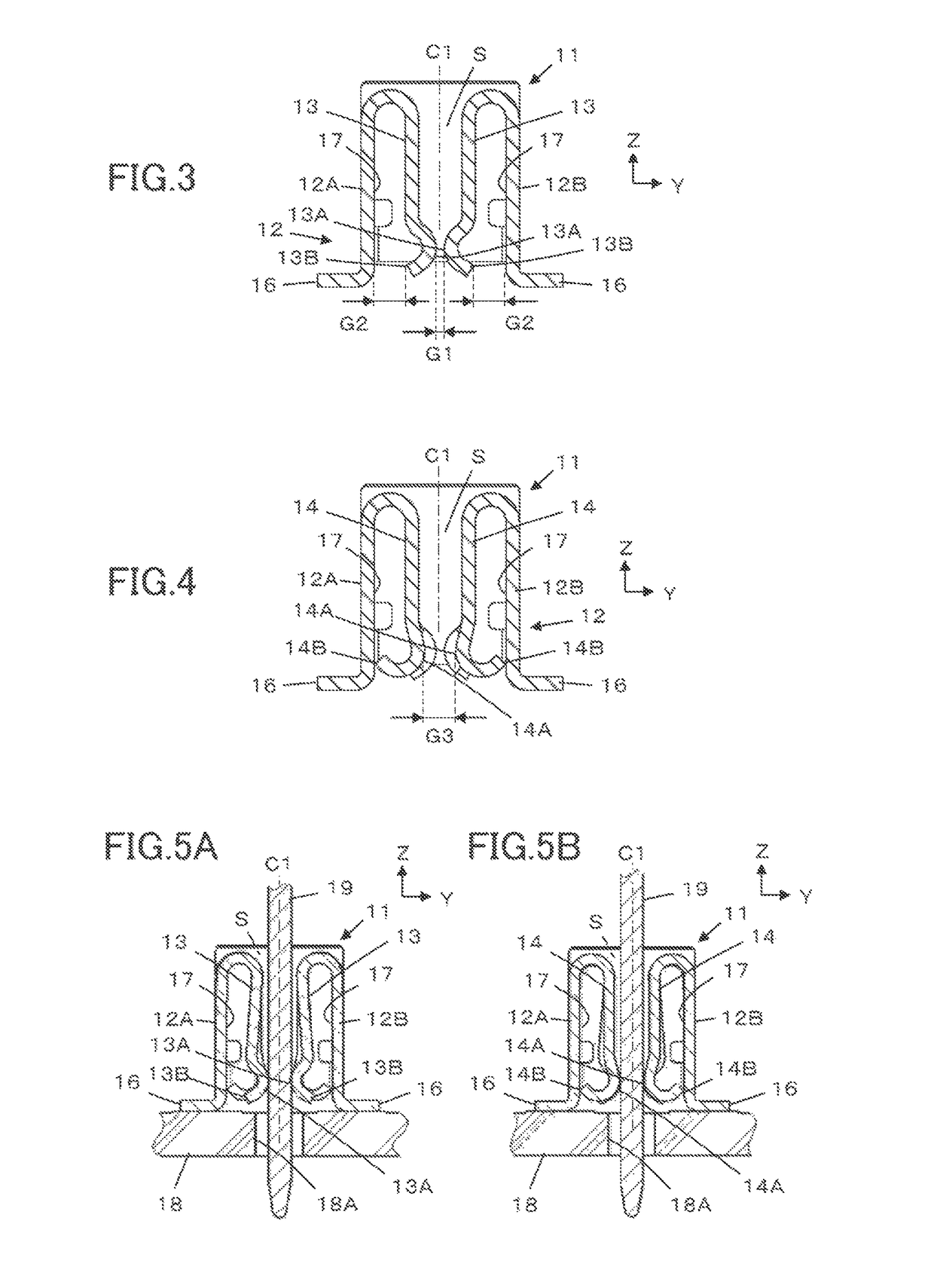
[0026]FIGS. 1A to 1D each illustrate a structure of a socket contact 11 of a connector according to Embodiment 1. The socket contact 11 is to be electrically connected to a counter-connector contact having a plate shape that is inserted along a fitting plane C1, and has a main body portion 12 made from a metal plate that is bent into a box shape. The main body portion 12 includes a front part 12A and a rear part 12B facing each other, and a pair of side surface parts 12C and 12D each joining ends of the front part 12A and ends of the rear part 12B, whereby a reception part S is formed inside the main body portion 12 to receive a counter-connector contact.

[0027]In addition, the socket contact 11 has two pairs of conduction spring pieces 13 that are respectively bent at the upper ends and on both sides of the front part 12A and of the rear part 12B of the main body portion 12 toward the inside of the reception part S and a pair of displacement regulators 14 that are respectively bent ...

embodiment 2

[0057]In the socket contact 11 in Embodiment 1, the front part 12A and the rear part 12B of the main body portion 12 each have two conduction spring pieces 13 disposed on both sides of one displacement regulator 14. However, this is not the sole case.

[0058]In a socket contact 21 of a connector according to Embodiment 2 as illustrated in FIG. 7, a front part 22A and a rear part 22B of a main body portion 22 each have two displacement regulators 24 disposed on both sides of a conduction spring piece 23. That is, the socket contact 21 has a pair of conduction spring pieces 23 and two pairs of displacement regulators 24. Each of the conduction spring pieces 23 and each of the displacement regulators 24 are constituted as identical to the conduction spring piece 13 and the displacement regulator 14 used in Embodiment 1, respectively.

[0059]Having such constitution, the socket contact 21 can realize reliable electrical conduction similarly to the socket contact 11 in Embodiment 1, even if ...

embodiment 3

[0061]In the socket contact 11 in Embodiment 1, the soldering parts 16 are joined to the lower ends of the front part 12A and the rear part 12B of the main body portion 12 respectively so as to face each other across the fitting plane C1. However, as in a socket contact 31 of a connector according to Embodiment 3 illustrated in FIGS. 8A and 8B, soldering parts 36 can be joined to the lower ends of a pair of side surface parts 12C and 12D of the main body portion 12 respectively such that a pair of the soldering parts 36 are disposed to face each other in the direction along the fitting plane C1.

[0062]In the socket contact having such constitution, the soldering parts 36 extending in the Y direction along the side surface parts 12C and 12D are formed. Therefore, a force acting on the conduction spring pieces 13 and the displacement regulators 14 generated by insertion of the counter-connector contact 19 and positional deviation of the contact 19 is received by the soldering parts 16 ...


PUM


Abstract

A connector has a socket contact to be electrically connected to a counter-connector contact, the socket contact including: one or more pairs of conduction contact points disposed respectively on both sides of a fitting plane in an elastically displaceable manner; and one or more pairs of displacement regulator contact points disposed respectively on both sides of the fitting plane and coming into contact with the counter-connector contact when the counter-connector contact shifts, the one or more pairs of conduction contact points and the one or more pairs of displacement regulator contact points are disposed side by side in a direction along the fitting plane at a substantially same depth in a fitting direction, each of the pairs of displacement regulator contact points having a gap therebetween larger than that in each of the pairs of conduction contact points.

Description

BACKGROUND OF THE INVENTION[0001]The present invention relates to a connector, in particular, to a connector having a socket contact to be electrically connected to a counter-connector contact having a plate shape.[0002]The socket contact of a connector of this type has a spring contact point capable of elastic displacement. At the time of engagement of connectors, a counter-connector contact is inserted into the socket contact relatively along a fitting plane and comes into contact with the spring contact point of the socket contact, while elastically shifting the spring contact point. Due to the elastic force generated at the spring contact point at this time, the socket contact is electrically connected to the counter-connector contact.[0003]However, in a case where insertion position is improper, such as when the counter-connector contact is inserted off the fitting plane or inserted obliquely with respect to the fitting plane, the spring contact point of the socket contact poss...

Claims


Application Information

Patent Timeline
Patent Type & Authority Patents(United States)
IPC IPC(8): H01R11/22H01R13/11H01R4/02H01R12/71H01R4/16H01R13/115
CPCH01R13/11H01R4/02H01R4/16H01R12/718H01R13/113H01R13/115H01R12/57
Inventor HASHIGUCHI, OSAMUSHIMENO, RYUZO
Owner JAPAN AVIATION ELECTRONICS IND LTD
Why Eureka
Try Eureka