Injection zone markers for biomedical implants

a biomedical implant and injection zone technology, applied in the field of implantable devices, can solve the problems of difficult to accurately locate the injection element through the overlying tissue, expander leakage, additional pain and discomfort for patients,

Active Publication Date: 2017-05-02
MENTOR WORLDWIDE
View PDF26 Cites 14 Cited by
  • Summary
  • Abstract
  • Description
  • Claims
  • Application Information

AI Technical Summary

Problems solved by technology

It can be difficult, however, to accurately locate the injection element through the overlying tissue once the expander has been implanted.
If the injection element is missed and the needle punctures the shell of the tissue expander, the expander can leak, which typically requires removal and replacement of the expander.
It still can be difficult, however, to identify the proper location through tissue, and a raised palpation ring may cause additional pain and discomfort to the patient.
Systems and methods of the types described above are not ideal.
Magnetic field based detection systems incorporate magnets or metallic parts, which may be undesirable to some patients, and which result in difficulties in passing through airport security or undergoing MRI procedures, etc.
Radiographic detection systems require additional exposure to radiation, which is undesirable.
Further, these types of devices require additional parts, which add to the cost of the expander itself.

Method used


Image

  • Injection zone markers for biomedical implants
  • Injection zone markers for biomedical implants
  • Injection zone markers for biomedical implants

Examples


Embodiment Construction

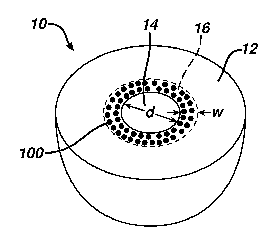
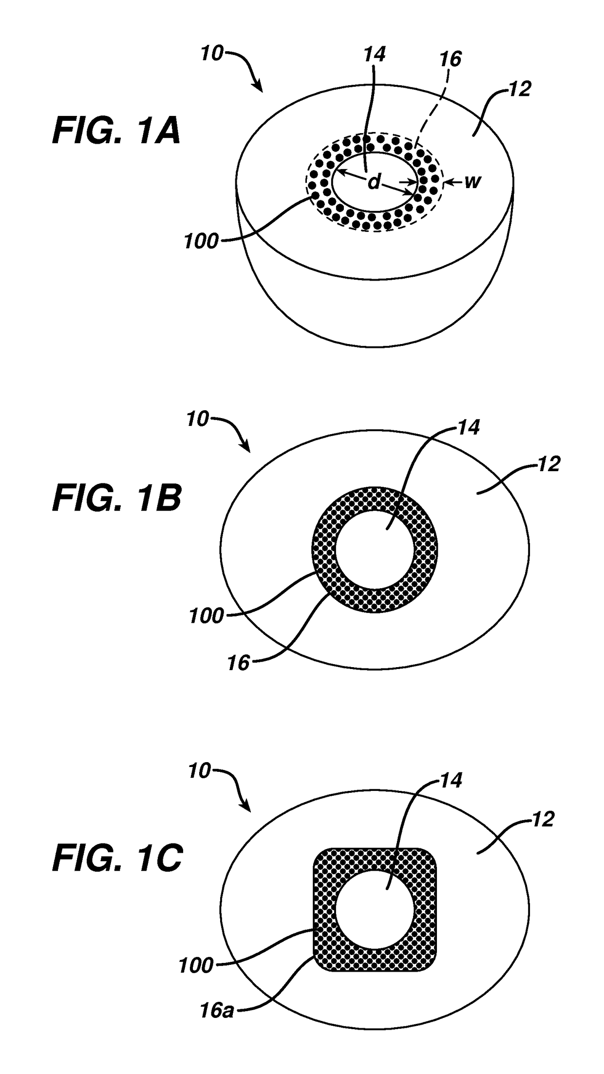
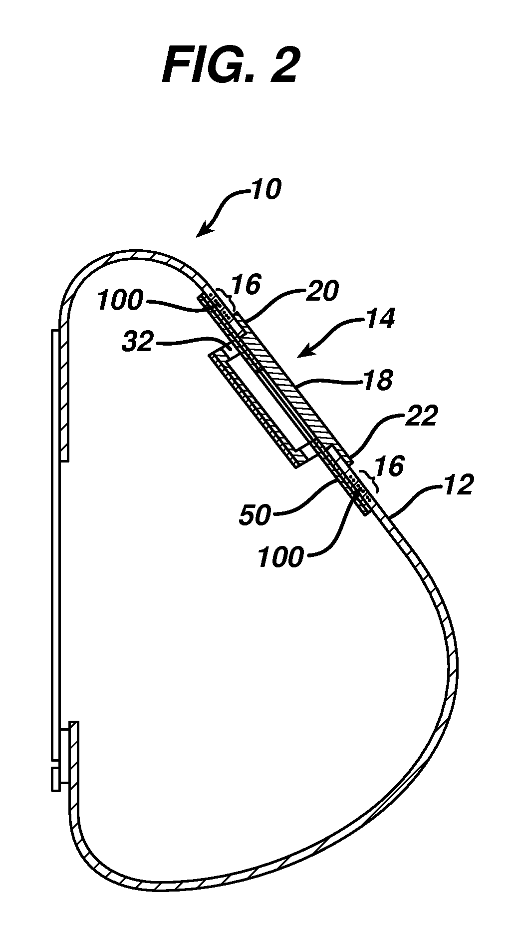
[0033]In the following are described various embodiments of a mammary implant, such as a mammary tissue expander, with markers according to the present invention. Where like elements have been depicted in multiple embodiments, identical or similar reference numerals have been used for ease of understanding.

[0034]As indicated, the present invention relates to implants having markers for more readily detecting the location of the implant, or portions thereof, once implanted within a patient. Exemplary implants having such markers will first be generally described below, followed by a more detailed description of the markers themselves and various methods for integrating such markers into implants, and methods for their use.

[0035]The invention described below leverages the general, well known concept that the difference between solid or liquid vs. gas can be detected by ultrasound. It is further known that small air bubbles on a gelatin surface can be detected by ultrasound within limi...


PUM


Abstract

A mammary implant and method of making are provided herein. The implant includes an outer shell configured to retain fluid therein, an injection element coupled to the outer shell and adapted to receive therethrough an injection device for injecting fluid into the outer shell, and an injection marker zone made of a material having ultrasonically detectable markers incorporated therein. The markers are a plurality of microcavities that are located relative to the injection element so that, when ultrasonically detected, such detection indicates a location of the injection element.

Description

BACKGROUND OF THE INVENTION[0001]The present invention relates to implantable devices, and more particularly to tissue expanders and prostheses having markers to assist in locating the implant or selected area(s) of the implant once implanted. Although the tissue expanders may be used in other areas of the body, one specific application is mammary implants such as soft tissue expanders.[0002]Tissue expanders are devices that are implanted beneath the skin or muscle and then gradually inflated to stretch the overlying tissue. Expanders are commonly used either to create a pocket for receiving a permanent prosthesis, or to generate an increased skin surface area in anticipation of the new skin being utilized for grafting or reconstruction.[0003]Conventional implantable mammary tissue expanders are formed of a silicone polymer shell. After implantation, a fluid, such as saline, is periodically injected into the expander to enlarge it over time. Between injections, the surrounding skin ...

Claims


Application Information

Patent Timeline
Patent Type & Authority Patents(United States)
IPC IPC(8): A61F2/12A61B8/08
CPCA61F2/12A61B8/481A61F2250/0069A61F2250/0098A61F2240/001A61F2250/0003A61F2250/0096A61F2250/0097A61F2250/001
Inventor HRISTOV, KRASIMIRAKRIKSUNOV, LEO B.TANNHAUSER, ROBERT J.
Owner MENTOR WORLDWIDE
Why Eureka
Try Eureka